Paravan Space Drive II User Manual
Primary functions
Hide thumbs
Also See for Space Drive II:
- Operating instructions manual (58 pages) ,
- Maintenance manual (32 pages)
Table of Contents
Advertisement
Quick Links
Advertisement
Table of Contents

Subscribe to Our Youtube Channel
Related Manuals for Paravan Space Drive II


Summary of Contents for Paravan Space Drive II
- Page 1 Paravan Space Drive II User‘s manual Primary Functions www.paravan.com EN/US V2.0...
- Page 2 Valid for the following models: Paravan Space Drive II System Publisher and copyright: PARAVAN GmbH Date of issue: 1.8.2016 Document number: Benutzer_SD_Primaer_V2_EN-US...
- Page 3 Manual in a handy place in your vehicle for later reference. Our user manual contains answers to questi- ons relating to the equipment, operation and care of the PARAVAN SPACE DRIVE II driving system. It you should have any questions or suggestions about the PARAVAN SPACE DRIVE II driving system, please do not hesitate to contact us.
-
Page 4: Table Of Contents
Table of contents General Details of publisher .....................10 Your manufacturer ........................10 1.1.1 Copyright ..........................11 On this User's Manual ..................12 General issues .......................... 12 2.1.1 Driving direction information ....................12 2.1.2 Technical status of this documentation ................. 13 2.1.3 Trademark .......................... - Page 5 Information Details relating to the product................36 The serial number ........................36 Overview of the SPACE DRIVE II driving system ...........37 Definition of terms for parts and their positions ..............37 Operating and control elements ................39 General information regarding operating elements............... 39 7.1.1...
- Page 6 The vehicle is delivered to you as follows ................50 8.2.1 Settings on the vehicle ......................51 Preparation of the vehicle for driving ..............52 Driving with the PARAVAN SPACE DRIVE driving system ............. 52 9.1.1 Put the locking pin in the correct position................54 9.1.2 Align the steering and the steering servo-motor ..............
- Page 7 10.3.1 Mini-steering-wheel ......................... 70 10.3.2 Steering joystick (2-way) ......................71 10.3.3 Rotational steering unit ......................72 10.4 Operating the accelerator/brake function and the steering function ........73 10.4.1 Accelerator/brake and steering joystick (4-way) ..............73 Operating the Check Control ................74 11.1 Navigation in the menu structure ...................
- Page 8 Initial steps, fault search ......................92 16.2 Fault message .......................... 93 Emergency mode ....................94 17.1 Accident............................ 95 Your contact to the PARAVAN customer service ..........96 18.1 Hotline ............................96 Technology Electrical system ....................97 19.1 Notes on the power supply ..................... 97 19.1.1...
- Page 9 Fig. 2: Serial number ........................... 36 Fig. 3: Overview ........................... 37 Fig. 4: Components ..........................38 Fig. 5: PARAVAN main module ......................40 Fig. 6: Check control ........................... 45 Fig. 7: Accelerator/brake lever ......................46 Fig. 8: Two-way joystick ........................46 Fig.
- Page 10 Fig. 15: Fuses, mechanical ........................59 Fig. 16: System switch .......................... 60 Fig. 17: Locking pin ..........................60 Fig. 18: Unlocking bolt .......................... 61 Fig. 19: Locking pin ..........................61 Fig. 20: Fasten seat belt, logo ......................63 Fig. 11: Sequence of steps ........................
- Page 11 Fig. 17: Backup battery ......................... 100 Fig. 18: Button for external charging ....................101 Fig. 19: Certification for lithium battery ....................105 Table of illustrations...
-
Page 12: Details Of Publisher
General Details of publisher Your manufacturer PARAVAN GmbH Main office / HQ/ Production Plant Paravanstraße 5-10, D-72539 Pfronstetten-Aichelau Phone: +49 (0) 73 88 / 99 95-91 › Fax: +49 (0) 73 88 / 99 95-999 › Email: info@paravan.com › Fig. 1: QR Code Internet: www.paravan.com › Managing director: Roland Arnold › Many mobile phones and PDAs contain an integrated camera... -
Page 13: Copyright
Federal Republic of Germany dated 9 September 1965 in its currently valid version. It is generally subject to charges. Any infringements will be subject to the penal clauses of the aforementioned copyright law. Copyright © PARAVAN GmbH 2014. All rights reserved! › Details of publisher... -
Page 14: On This User's Manual
All product features mentioned for different versions and functions may be combined with each other and may devi- ate from the standard version. This User's Manual is an integral part of the PARAVAN SPACE Fig. 2: Direction of travel... -
Page 15: Technical Status Of This Documentation
June 2014. The User's Manual for the PARAVAN SPACE DRIVE II driving system was compiled in German and may be translated into other languages. In the event of any discrepancies, the German version will be legally binding. -
Page 16: Trademark
The brand SPACE DRIVE® designates the in- dividual components and the complete uniform electronic, digital driving system of the company PARAVAN GmbH. This trademark guarantees the quality of the driving system. Only PARAVAN GmbH is entitled to use the designations PARAVAN®... -
Page 17: Disclaimer
Disclaimer Operation of the PARAVAN SPACE DRIVE II without errors and faults can only be guaranteed when the infor- mation provided in this User's manual is considered and implemented. PARAVAN GmbH does not accept any liability or give any guarantee regarding damage or malfunctions that result during operation when the instructions in this User's Manual are not adhered to or when the PARAVAN SPACE DRIVE II is altered. -
Page 18: Guarantee
2.2.1 Guarantee Guarantee cover is exclusively defined by the respective PARAVAN warranty conditions. Explicitly excluded from warranty claims is any damage resulting from: Wear and tear › Inappropriate operation or use › Incorrect/Irregular maintenance › Incorrect/Irregular care › See your personal "Guarantee card"... -
Page 19: Technical Alterations
2.2.2 Technical alterations Any modifications made to the safety equipment and technical changes to the PARAVAN SPACE DRIVE II driving system, however small, are strictly prohibited. All alterations must be executed by PARAVAN GmbH. PARAVAN GmbH reserves the right to make technical alterations and improvements to the product in the interests of our customers and as a result of advancing technology. - Page 20 WA R N I N G Risk of personal injury when operating the vehicle with a dri- ving system that does not correspond to the original or delive- ry state. Physical damage to the vehicle or the driving system due to non-authorized or incorrectly installed components.
-
Page 21: Target Groups
› Have a valid driving license in the respective country of operation. › Know the contents of the User's Manual in order to operate a vehicle with a PARAVAN SPACE DRIVE II driving system safely and to drive it. ›... -
Page 22: Explanation Of Symbols
Explanation of symbols You will come across the following symbols and warning signs while reading the User's Manual. The "Caution, Danger" logo Calls your attention to danger points. The preventative measures contained in the associated text must al- ways be followed. This symbol always appears with an associated signal word which indicates the level of danger. -
Page 23: Structure Of Safety Notices
2.4.1 Structure of safety notices You can find the following information in the safety notes: Warning or hazard symbol . › Type and source of hazard . › Signal word . › Consequences of occurrence . › Preventative action . -
Page 24: Safety Note
Safety note General safety notes You must under all circumstances observe the following safety notes for your own safety, for that of people in your vicinity and to protect the environment. D A N G E R! Mortal danger for persons operating the vehicle with a SPACE DRIVE driving system that does not correspond to the original or delivery state. - Page 25 D A N G E R! Mortal danger for persons operating the vehicle with a SPACE DRIVE driving system when the safety pin is not inserted in the steering servo-motor. Mortal danger for persons who have not been instructed and therefore lose control of the vehicle.
- Page 26 D A N G E R! Mortal danger for persons driving a vehicle with a SPACE DRIVE system when the vehicle and the drive system are not subject to regular inspection. Mortal danger for all persons who lose control of their vehicle due to inappropriately performed maintenance, inspection or repair work.
- Page 27 WA R N I N G Risk of injury for persons operating the vehicle with a SPACE DRIVE driving system that does not correspond to the original or delivery state. Physical damage to the vehicle or the SPACE DRIVE system due to non-authorized or incorrectly installed components.
- Page 28 WA R N I N G Risk of injury for persons who operate the vehicle in emergen- cy mode after failure of power support systems e.g. steering pump, servo-pump. Damage to the vehicle in emergency mode due to failure of power support systems, e.g.
- Page 29 WA R N I N G Risk of injury for persons operating the vehicle with a SPACE DRIVE driving system that does not correspond to the original or delivery state. Physical damage to the vehicle or the SPACE DRIVE system due to non-authorized or incorrectly installed components.
-
Page 30: Functional Description
Manufacturing standard 4.1.1 General issues The PARAVAN SPACE DRIVE II driving system is a modular control system that controls the primary systems accelerator, brake and steering by multi-channel digital communication. The operator (driver) of the vehicle has the option of entering appropriate sensor specifications into the primary systems or the input devices that will then be executed by the controllers (PARAVAN main module) or the actuators (accelerator and brake servo-motors). -
Page 31: Equipment Characteristics Of The Driving System
4.1.2 Equipment characteristics of the driving system The PARAVAN SPACE DRIVE II driving system includes several servo- motors that move according to controller signals (PARAVAN main mo- dule): A double-servo-motor for moving the accelerator and the brake › pedal A double-servo-motor for moving the steering wheel ›... -
Page 32: Standards And Directives Applied
4.1.3 Standards and directives applied The PARAVAN SPACE DRIVE II driving system only makes use of system components that are qualified ac- cording to the AEC (Automotive Electronics Council). The AEC is an organization for standardising the qualification of electronic components in the au- tomotive industry. -
Page 33: Appropriate Usage
Appropriate usage A vehicle with an active or passive PARAVAN SPACE DRIVE II driving system may only be used in public road traffic by persons who have a valid driving licence in the respective country of operation. Vehicles with a PARAVAN SPACE DRIVE II driving system are exclusively intended for the application areas and use described in the Chapter "Use of the vehicle with driving system". -
Page 34: Use Of A Vehicle With A Driving System
4.2.1 Use of a vehicle with a driving system - unproblematic The vehicle and the SPACE DRIVE II driving system are in their original or delivery state. › Participation in public road traffic according to the legal stipulations in the country of operation, e.g. Road ›... -
Page 35: Approvals, Certifications
Europe at the United Nations. The contract parties (countries) accept the ECE regulations and permit the use and import of ECE type-tested vehicles and parts. The PARAVAN SPACE DRIVE II driving system has the following ECE Fig. 7: ECE marking... -
Page 36: Battery Used
4.3.2 Battery used PARAVAN GmbH uses lithium-iron-phosphate batteries. They are a type of lithium-iron batteries. Lithium- iron-phosphate (LiFePO) is used as a cathodic material instead of the conventional cathodes. They are harm- less as long as the batteries have no mechanical defects. -
Page 37: Emv Test
The electromagnetic compatibility (EMC) defines the ability of a device to work reliably in an electromagnetic environment without unduly exposing this environment to electromagnetic effects. The PARAVAN SPACE DRIVE II driving system has the following ECE homologation: ECE-R-10 Rev. 04 Test Report P130468 ›... -
Page 38: Information
The serial number The PARAVAN product is identified by an 11-digit serial number. All individual system components can be identified by the serial num- ber and allocated to the respective PARAVAN SPACE DRIVE II driving system. D082.01.00.016 It is very important to mention the serial number in all correspondence with PARAVAN GmbH to ensure that you receive technically correct ad- vice. -
Page 39: Overview Of The Space Drive Ii Driving System
Definition of terms for parts and their positions The following terms for components and parts will be used in this User's Manual. The location of the PARAVAN SPACE DRIVE II driving system elements in the vehicle may vary, but the elements are located in direct reach of the operator (driver). -
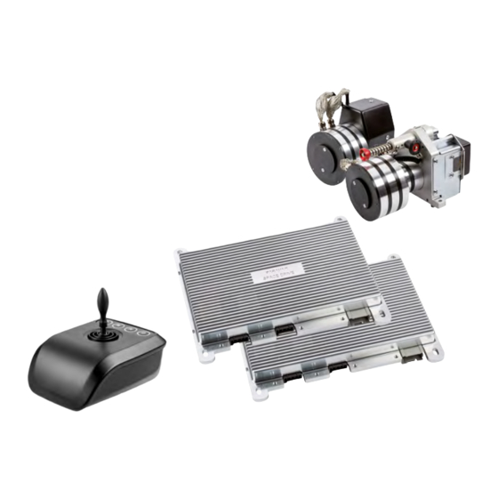
Page 40: Fig. 4: Components
The following terms for components and parts will be used in this User's Manual. The location of the PARAVAN SPACE DRIVE II dri- ving system elements in the vehicle may vary due to the availability of space in the vehicle. -
Page 41: Operating And Control Elements
Operating and control elements General information regarding operating elements PARAVAN GmbH provides a broad offer of operating elements in the PARAVAN SPACE DRIVE II section. The- se operating elements are generally based on four controller types: Accelerator/brake lever for acceleration/braking function ›... -
Page 42: Control And Monitoring Of The Driving System
› rotation dampers. › The PARAVAN SPACE DRIVE II driving system is programmed to use different parameters for different speeds. It is therefore possible to change the sensitivity of the operating elements as a function of speed. This implies: A large movement of the operating element (steering device) may/ ›... -
Page 43: Overview Of Operating Elements
Fine adjustment of the system is achieved by changing the software parameters. Mechanical/electronic parameters may only be changed by authorized workshops! See Section "18 Your PARAVAN customer service contact" Operating and control elements... -
Page 44: Overview Of Operating Elements
7.2.1 Individual modules/elements Each of the listed, individual modules can be separately installed in the vehicle. In this case, there will only be a single PARAVAN main module in the vehicle. List of the individual modules and their respective description (abbreviation): Two-way accelerator/brake slider ›... -
Page 45: Possible Combinations Of The Individual Modules
7.2.2 Possible combinations of the individual modules The PARAVAN SPACE DRIVE II driving system was designed to facilitate the combination of indivi- dual system elements according to the needs of the operator. PARAVAN GmbH can provide the following system combinations:... -
Page 46: Orthopaedic Extensions
The operating elements can be equipped with a variety of orthopaedic extensions to achieve optimal operating efficiency for the user. PARAVAN GmbH offers suitable extensions for any type of handicap. The extensions listed represent only some of the extensions available. -
Page 47: Overview Of Operating Elements
An internal CAN interface is used for communication between the Check Control and other modules, e.g. to the PARAVAN main module for facto- ry and software updates. Operating and control elements... -
Page 48: Accelerator/Brake Lever And Two-Way Joystick
7.4.2 Accelerator/brake lever and two-way joystick The accelerator/brake slider operating element completely controls and manages the accelerator and brake function › based on deflection with parameter-controlled distance and force. See Section "7.1.2 Force adjustment of the operating ele- ments" Fig. 7: Accelerator/brake lever The two-way joystick allows setting the accelerator and brake function... -
Page 49: General Information Regarding Operating Elements
General information regarding operating elements Maintenance work on control elements may only be perfor- med by certified dealers or certified SPACE DRIVE II technici- ans. Maintenance and repair work may only be performed by trained persons. Never attempt to perform maintenance and... -
Page 50: Function Of The Operating Elements
This implies that an powered vehicle equipped by PARAVAN with a PARAVAN SPACE DRIVE II driving system can at any time also be used by non-handicapped persons. The force connection between the steering servo-motor and the original steering column must be separated for this purposes. -
Page 51: Accelerator And Brake Servo-Motor
7.6.2 Accelerator and brake servo-motor The accelerator and brake servo-motor is mounted on an attachment beam in the load-carrying structure of the vehicle. The accelerator and brake servo-motor handles two functions: A Bowden cable pulls via a deflection mechanism on the driving pedal and thus increases speed. The pro- ›... -
Page 52: Delivery Of The Vehicle
Delivery of the vehicle Receiving your new/altered vehicle Check your vehicle with PARAVAN SPACE DRIVE II driving system for completeness and compare the deli- very state with the order documentation. Contact PARAVAN GmbH immediately when you have any doubt! Visually check that your vehicle is in an appropriate state. Immediately report any damage that may be due... -
Page 53: Settings On The Vehicle
However, if further adjustments should be necessary, they can be made at any time. Your PARA- VAN SPACE DRIVE II has been designed to allow adaptation to all aspects of your body measurements and operating strength, so that optimal reach and handling of the operating elements is ensured. -
Page 54: Preparation Of The Vehicle For Driving
Preparation of the vehicle for driving Driving with the PARAVAN SPACE DRIVE driving system The PARAVAN SPACE DRIVE II driving system must be electrically and mechanically activated in order to make full use of it. The following work steps must be performed: 1. -
Page 55: Fig. 5: Steering Not Switched On
PARA- VAN SPACE DRIVE driving system. Fig. 5: Steering not switched on 3. Starting the driving system. See Section "10 Operating the PARAVAN driving system" Fig. 6: Check Control display Preparation of the vehicle for driving... -
Page 56: Put The Locking Pin In The Correct Position
9.1.1 Put the locking pin in the correct position 1. Remove the locking pin from the steering servo-motor. -> Press and hold the internal button of the locking pin. -> Pull out the locking pin. 2. Perform the "Align steering and steering servo-motor" work steps. See Section "9.1.2 Align steering and steering servo-motor"... -
Page 57: Fig. 8: Locking Pin
The unlocking bolt is spring-loaded and automatically pushes back to the initial position! The locking pin must latch automatically. Only this will ensure that the steering servo-motor and the steering column are mechanically linked to each other in an appropriate way! 4. -
Page 58: Fig. 9: Locking Pin
6. Check that the locking pin has latched -> Change the position of the locking pin as required. Driving without the locking pin is prohibited! See Section "10 Operating the PARAVAN driving system" Fig. 9: Locking pin Preparation of the vehicle for driving... -
Page 59: Align The Steering And The Steering Servo-Motor
9.1.2 Align the steering and the steering servo-motor The following message will be shown on the Check Control display: Electrical steering Electrical steering not locked!!! Drive without? Yes / No › not locked!!! Drive without? The position of the vehicle steering and the position of the steering servo-motor do not correspond. -
Page 60: Fig. 12: Latch Steering
The PARAVAN SPACE DRIVE II driving system (steering servo- motor) will automatically and independently move to the middle steering position. Please latch After successful alignment or when the driving system has reached the steering and confirm middle position or when it is already in this position, the display of the... -
Page 61: Fig. 14: Start Screen
After successful alignment or when the PARAVAN SPACE DRIVE II dri- ving system has reached the middle position or when it is already in this position, the display of the Check Control operating element will show the start screen. Space Drive 2 The vehicle steering and the PARAVAN SPACE DRIVE II driving system are now calibrated to match each other. -
Page 62: Driving Without The Paravan Space Drive Driving System
There are some situations in which it is necessary to switch off the PARAVAN SPACE DRIVE II driving system. The PARAVAN SPACE DRIVE II driving system must be electrically and mechanically deactivated. The following work steps must be perfor- med:... -
Page 63: Fig. 18: Unlocking Bolt
5. Separate the link between steering servo-motor and steering co- lumn. -> Press and hold the locking pin. -> Push the unlocking bolt downwards. -> Release the locking pin. The locking pin must automatically latch! 6. Insert the locking pin into the steering servo-motor -> Keep pres- sing the inner button of the ... -
Page 64: Insurance, Personal Liability Insurance
Insurance, personal liability insurance We recommend to contact your insurance advisor before starting to use the vehicle, so that the use of the vehicle can be included in your insurance policies – in particular in your personal liability insurance. Please note that the vehicle may have to be insured in order to use it in public road traffic according to local legislation. -
Page 65: Functional Checking Before Driving
Functional checking before driving For your own safety, you must check the following points before each drive. Start and stop function (brakes) of the vehicle. › Function of the lighting system of the vehicle. › You may need to involve a second person for such a check. See "User's Manual"... -
Page 66: Operating The Paravan Driving System
Operate 10. Operating the PARAVAN driving system 10.1 Starting the driving system, sequence of steps 10.1.1 Before starting the motor Switch on the ignition. › ****************** PARAVAN Technology The starting menu is shown. Space Drive 2 › Detected devices: Device connection is queried and shown. -
Page 67: Fig. 12: Sequence Of Steps
The voltage of the secondary (backup) battery is shown. › 13.8 V Please start the vehicle motor! Request to start the vehicle motor. › Start the vehicle motor. -> Vehicle motor is running. Fig. 12: Sequence of steps Operating the PARAVAN driving system... -
Page 68: After Starting The Motor
Move the input device to the neutral position! Bring input device into neutral position. › Accelerator/brake test: Please move the input device in BRAKEdirection! Accelerator/brake test, follow the instructions. › Fig. 13: Sequence of steps Operating the PARAVAN driving system... -
Page 69: Fig. 14: Sequence Of Steps
SPACE DRIVE 2 System start of the driving system completed. › 0 Km/h The vehicle with the PARAVAN driving system is ready to drive. Fig. 14: Sequence of steps Operating the PARAVAN driving system... -
Page 70: Operating The Accelerator And Brake Function
The vehicle will execute the command. Braking; the vehicle reduces › driving speed and might finally come a standstill. Accelerating; the vehicle drives or picks up speed. Fig. 15: Accelerator/brake joy stick See Section "7.1.2 Force adjustment of the operating elements" Operating the PARAVAN driving system... -
Page 71: Accelerator/Brake Lever (2-Way)
The vehicle will execute the command. Braking; the vehicle reduces › driving speed and might finally come a standstill. Accelerating; the vehicle drives or picks up speed. Fig. 16: Accelerator/brake lever See Section "7.1.2 Force adjustment of the operating elements" Operating the PARAVAN driving system... -
Page 72: Operating The Steering Function
The mini-steering-wheel may be equipped with a variety of different or- thopaedic extensions, depending on the level and the type of disability, e.g.: Ball › Cone › Cylinder, etc. › See Section "7.3 Orthopaedic extensions" Operating the PARAVAN driving system... -
Page 73: Steering Joystick (2-Way)
The vehicle will execute the command. The running wheels turn to › the right, follow a right bend. The running wheels turn to the left, drive a left bend. See Section "7.1.2 Force adjustment of the operating elements" Fig. 18: Steering joystick Operating the PARAVAN driving system... -
Page 74: Rotational Steering Unit
Swiveling movement to the right (right bend). -> Running wheels turn › to the right. Swiveling movement towards the left (left bend). -> Running wheels › turn to the left. Fig. 19: Rotational steering unit See Section "7.1.2 Force adjustment of the operating elements" Operating the PARAVAN driving system... -
Page 75: Operating The Accelerator/Brake Function And The Steering Function
Fig. 20: 4-way joystick drive a left bend. See Section "7.1.2 Force adjustment of the operating elements" To prevent the wheelchair from moving in an undesirable way, do not provide any sudden drive commands when using the joystick! Operating the PARAVAN driving system... -
Page 76: Operating The Check Control
11. Operating the Check Control 11.1 Navigation in the menu structure The Check Control is the communication element for the driving system. Operator and service technicians can use the SEL push buttons to call up the basic information of the driving system after the system has been started. -
Page 77: Menu Structure Of The Check Control
11.1.1 Menu structure of the Check Control After pressing the SEL push button, the start menu (customer menu) is shown. It is now possible to select 6 further menus by pressing the push buttons. The menu structure is arranged in a clockwise sequence as follows: Battery voltages ›... -
Page 78: Customer Menu
12. Customer menu 12.1 Battery voltages Customer menu The customer menu is shown. › Continue with SEL. Battery voltages The "battery voltages" menu screen is shown. › Continue with SEL. Voltages Main battery: 13.9 V The battery voltages are shown. ›... -
Page 79: Fine-Calibration Of The Steering
12.2 Fine-calibration of the steering Continue with Fine calibration Steering The "fine calibration steering" menu screen is shown. › Continue with SEL. L-fine-calibration The "L-fine-calibration" menu screen is shown. › L-fine-calibration The L-fine-calibration menu screen is shown on the left or right side. ›... -
Page 80: Software Version
12.3 Software version Continue with Software version The "software version" menu screen is shown. › Software version Continue with SEL. X.XX The current software version is shown. › Continue with ESC. Fig. 25: Software version Jump back to the previous menu. ›... -
Page 81: Maintenance Intervals
12.4 Maintenance intervals Continue with Maintenance intervals The "maintenance interval" menu screen is shown. › Continue with SEL. Maintenance interval - Remaining time Remaining time of maintenance interval is shown. › +00:00:00 Continue with ESC. Fig. 26: Maintenance intervals Jump back to the previous menu. ›... -
Page 82: Date And Clock
12.5 Date and clock Continue with Date and clock The "date and time" menu screen is shown. › Continue with SEL. Date / time Tu 27/05/2014 The current date and the time are shown. 16:17:45 › Continue with ESC. Fig. 27: Date / time Jump back to the previous menu. -
Page 83: Button Illumination, Color
12.6 Button illumination, color Continue with Button illumination The "button illumination" menu screen is shown. › Continue with SEL. Button illumination The "button illumination colour" menu screen is shown. Colour › Continue with SEL. Button illumination Color: cyan The "button illumination colour: cyan" menu screen is shown. Se- ›... -
Page 84: Button Illumination Day
12.7 Button illumination, day Continue with Button illumination The "button illumination, day" menu screen is shown. › Continue with SEL. Button illumination Day brightness: 80% The "button illumination, day brightness" menu screen is shown. › Change the value with Fig. 29: Button illumination Continue with ESC. -
Page 85: Button Illumination Night
12.8 Button illumination night Continue with Button illumination Night The "button illumination, night" menu screen is shown. › Continue with SEL. Button illumination Night brightness: 20% The "button illumination, night brightness" menu screen is shown. › Change the value with Fig. -
Page 86: Loading And Transporting Your Vehicle
13. Loading and transporting your vehicle Use a professional breakdown service in the event that your vehicle breaks down and has to be loaded onto a car transport trailer. The loading and securing of the vehicle is described in the User's Manual of the vehicle. Possible securing points, e.g. -
Page 87: Care And Maintenance
The earliest deadlines in the maintenance plan apply. This includes regular intervals in years (time) and specific performance parameters (operating hours). See "Maintenance instructions" Please get in touch with your certified dealer or contact PARAVAN GmbH directly in case you have any ques- tions. See Section "18 Your PARAVAN customer service contact"... - Page 88 D A N G E R! Mortal danger for persons driving a vehicle with a SPACE DRIVE system when the vehicle and the SPACE DRIVE system are not subject to regular inspection. Mortal danger for all persons who lose control of their vehicle due to inappropriately performed maintenance, inspection or repair work.
-
Page 89: Cleaning And Care
14.1 Cleaning and care No running water may be used for cleaning the modules (input devices and operating elements). Ensure that electronic parts cannot come into contact with water. Only use mild soaps solutions without abrasive additives to clean the module frame or the plastic ›... -
Page 90: Disposal And Environmental Protection
The PARAVAN SPACE DRIVE II driving system can be removed and recycled or disposed of in an environmentally compatible manner when the vehicle is no longer used. -
Page 91: Packaging Materials
15.1 Packaging materials The packaging is largely made of recyclable and environmentally harm- less materials, such as: Bubble wrap, › cardboard. › Take advantage of the opportunity to recycle the packaging in an environmentally friendly manner. Recycling of waste is preferable to disposing of it. -
Page 92: Re-Commissioning
15.2 Re-commissioning The following work steps have to be performed before re-operation when a vehicle with a PARAVAN SPACE DRIVE II driving system was not used for a prolonged period: Check all safety devices and repair them where necessary ›... -
Page 93: Notes On Transferring The Vehicle
15.3 Notes on transferring the vehicle All technical documentation required for safe handling and operation must be forwarded to the new owner when a vehicle with a PARAVAN SPACE DRIVE II driving system is transferred, e.g. sold. This includes: The User's Manual and ›... -
Page 94: Correcting Failures
Stop the vehicle without haste and in a place where it does not pose a traffic hazard if your PARAVAN SPACE DRIVE II driving system shows an error or fault. Do not stop the vehicle in a tunnel, on a railway crossing or in places with bad visibility. -
Page 95: Fault Message
When the fault message appears frequently or is shown permanently, visit a workshop and › contact PARAVAN. › See Section "18 Your PARAVAN customer service contact" Critical fault! Visit workshop! Fig. 17: Critical fault! Correcting failures... -
Page 96: Emergency Mode
17. Emergency mode For safety reasons, operation is only possible with limited speed when the vehicle is in emergency mode. WA R N I N G Risk of injury for persons who operate the vehicle in emergen- cy mode after the failure of power support systems e.g. stee- ring pump, servo-pump. -
Page 97: Accident
Do not use the vehicle before a maintenance inspection at a workshop when a vehicle with a PARAVAN SPACE DRIVE II driving system is involved in a traffic accident. The vehicle or components of the system may be damaged in a way that is not visible but may nevertheless lead to malfunction. -
Page 98: Your Contact To The Paravan Customer Service
18. Your contact to the PARAVAN customer service 18.1 Hotline Your Space Drive dealer will gladly help you with repairs or spare parts procurement for your PARAVAN vehicle system. Your contact to the PARAVAN customer service... -
Page 99: Electrical System
19.1 Notes on the power supply The PARAVAN SPACE DRIVE II driving system is equipped with a powerful, high-quality battery. This mainte- nance-free battery is completely sealed. The system is not designed to need or allow any refilling or topping up of the electrolyte (battery acid). -
Page 100: Starting The Vehicle With External Power
19.1.1 Starting the vehicle with external power Once the on-board voltage of the vehicle has dropped so far that it can only be started with external power, e.g. from a second vehicle, the vehicle must be connected or linked up according to the information of the vehicle manufacturer. -
Page 101: Charge The Batteries
19.2 Charge the batteries The voltage is monitored and independent charging may take place once the motor has been started. Manual charging of the batteries (vehicle and backup battery) is not necessary when you regularly operate your vehicle. It is recommended to connect the vehicle to a commercial battery charger, e.g. overnight, when the vehicle is rarely operated or when a prolonged standstill period is foreseen. -
Page 102: Notes On Maintenance Charge
19.3 Notes on maintenance charge Sealed batteries should never be opened. Opening the batter ies will cause irreparable damage to these components, possibly resulting in a complete failure of the power supply. See Section "21.1 Dealing with sealed batteries" Always connect your vehicle to the charger when it is not used for a prolonged period! Commercial chargers automatically switch to "Maintenance charge"... -
Page 103: Maintenance Charge
19.3.1 Maintenance charge The backup battery must be fully charged after approximate- ly 1 year without driving according to the specifications of the manufacturer. The external loading function must be activated/deactivated with the button while the ignition switched off. 1. -
Page 104: Technical Equipment
20. Technical equipment 20.1 Technical data Operating specifications Operating temperature -40°C to +85°C Storage temperature -40°C to +125°C Operating voltage 12 Volt +10.5V DC to +15V DC Current draw, typically approximately 7A per module Max. current draw 35 A per module (limited current draw) Cycle time 10 ms Technical equipment... -
Page 105: Replacement Parts
20.2 Replacement parts The replacement of original parts by third-pary components or by reproduction (copied) original parts is strictly forbidden! Obtain all your spare parts from your dealer or from PARAVAN GmbH. See Section "1.1 Your manufacturer" WA R N I N G... -
Page 106: Systems And Technical Documentation
21. Systems and technical documentation 21.1 Handling the sealed backup battery The backup battery of the PARAVAN SPACE DRIVE II driving system is a lithium-ion battery that is charged by the vehicle while driving, using internal load regulation. The lithium-ion battery is maintenance-free. -
Page 107: Certification For Lithium Battery
21.2 Certification for lithium battery 21.2.1 Copy of the certificate Fig. 19: Certification for lithium battery Systems and technical documentation... - Page 108 Notes: - - - - - - - - - - - - - - - - - - - - - - - - - - - - - - - - - - - - - - - - - - - - - - - - - - - - - - - - - - - - - - - - - - - - - - - - - - - - - - - - - - - - - - - - - - - - - - - - - - - - - - - - - - - - - - - - - - - - - - - - - - - - - - - - - - - - - - - - - - - - - - - - - - - - - - - - - - - - - - - - - - - - - - - - - - - - - - - - - - - - - - - - - - - - - - - - - - - - - - - - - - - - - - - - - - - - - - - - - - - - - - - - - - - - - - - - - - - - - - - - - - - - - - - - - - - - - - - -...
- Page 109 - - - - - - - - - - - - - - - - - - - - - - - - - - - - - - - - - - - - - - - - - - - - - - - - - - - - - - - - - - - - - - - - - - - - - - - - - - - - - - - - - - - - - - - - - - - - - - - - - - - - - - - - - - - - - - - - - - - - - - - - - - - - - - - - - - - - - - - - - - - - - - - - - - - - - - - - - - - - - - - - - - - - - - - - - - - - - - - - - - - - - - - - - - - - - - - - - - - - - - - - - - - - - - - - - - - - - - - - - - - - - - - - - - - - - - - - - - - - - - - - - - - - - - - - - - - - - - - -...
- Page 110 Notes: - - - - - - - - - - - - - - - - - - - - - - - - - - - - - - - - - - - - - - - - - - - - - - - - - - - - - - - - - - - - - - - - - - - - - - - - - - - - - - - - - - - - - - - - - - - - - - - - - - - - - - - - - - - - - - - - - - - - - - - - - - - - - - - - - - - - - - - - - - - - - - - - - - - - - - - - - - - - - - - - - - - - - - - - - - - - - - - - - - - - - - - - - - - - - - - - - - - - - - - - - - - - - - - - - - - - - - - - - - - - - - - - - - - - - - - - - - - - - - - - - - - - - - - - - - - - - - - -...
- Page 111 - - - - - - - - - - - - - - - - - - - - - - - - - - - - - - - - - - - - - - - - - - - - - - - - - - - - - - - - - - - - - - - - - - - - - - - - - - - - - - - - - - - - - - - - - - - - - - - - - - - - - - - - - - - - - - - - - - - - - - - - - - - - - - - - - - - - - - - - - - - - - - - - - - - - - - - - - - - - - - - - - - - - - - - - - - - - - - - - - - - - - - - - - - - - - - - - - - - - - - - - - - - - - - - - - - - - - - - - - - - - - - - - - - - - - - - - - - - - - - - - - - - - - - - - - - - - - - - -...
- Page 112 Paravan Space Drive System User‘s manual Primary Functions PARAVAN GmbH Paravanstraße 5-10 72539 Pfronstetten-Aichelau Germany Telefon: +49 (0) 73 88 / 99 95-60 Fax: +49 (0) 73 88 / 99 95-999 Email: info@paravan.com www.paravan.com EN/US V2.0...
Need help?
Do you have a question about the Space Drive II and is the answer not in the manual?
Questions and answers