
Subscribe to Our Youtube Channel
Related Manuals for Lumens OIP-D50C

Summary of Contents for Lumens OIP-D50C
- Page 1 OIP-D50C AVoIP Controller User Manual - English [Important] To download the latest version of Quick Start Guide, multilingual user manual, software, or driver, etc., please visit Lumens https://www.MyLumens.com/support...
-
Page 2: Table Of Contents
Table of Contents Chapter 1 Package Contents ..............2 Chapter 2 Instruction before installation ..........3 2.1 Selecting Switch ....................3 2.2 Bandwidth Calculation ..................3 Chapter 3 Product Overview ..............4 3.1 System Requirements ..................4 3.2 I/O functions Introduction ................4 3.3 Remote Control .................... -
Page 3: Chapter 1 Package Contents
Chapter 1 Package Contents Instruction for OIP-D50C Controller Remote Control installation Quick Installation Guide 5V/2.6A Power supply 3.5 mm to infrared (including a Foot mats extender multinational adapter) (A set of four) Terminal block Terminal block Terminal block (90° 3pin) (90°... -
Page 4: Chapter 2 Instruction Before Installation
Chapter 2 Instruction before installation 2.1 Selecting Switch Recommended Brand/Model Brand Model Brand Model NETGEAR S3300 Series ZyXEL GS1920 NETGEAR M4300 Series ZyXEL GS2210 D-Link DGS-1510 ZyXEL XS3700 Cisco Catalyst 2960-X Dell PowerConnect 5524 EtherWAN EX26262F Dell PowerConnect 2816 2.2 Bandwidth Calculation ... -
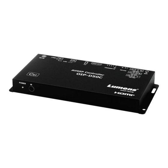
Page 5: Chapter 3 Product Overview
Chapter 3 Product Overview 3.1 System Requirements An effective network connection provided by a switch or router, used to connect this product and a compatible VoIP extender (including encoder and decoder). An HDMI audio and video equipment, such as a HD TV or screen. 3.2 I/O functions Introduction 3.2.1 Front panel Item... -
Page 6: Remote Control
3.3 Remote Control Preset locations 1 ~ 8: Press any key to start the corresponding preset location of that number. 3.4 IR Pin Assignment IR Extender Electricity Ground 3.5 RS-232 Pin and Default Setting Default Setting of the Serial Port Baud Rate 19200 Data Bit... -
Page 7: Chapter 4 Installation And Connections
Chapter 4 Installation and Connections 4.1 Connection diagram Control keyboard with a contactor Computers with serial ports or network ports Contactor input RS-232 input Special Local Area Network Connection Network Switch Remote Control IR input Power Supply Special VoIP Network Connection Network Switch HDMI output... -
Page 8: Chapter 5 Start Using
Chapter 5 Start Using 5.1 Switch Setting Notes VoIP transmission will consume a lot of bandwidth (high resolutions), and it needs to be paired with a Gigabit network switch that supports Jumbo Frame and IGMP (Internet Group Management Protocol) Snooping. It is strongly recommended to be equipped with a switch which includes VLAN (Virtual Local Area Network) professional network management. -
Page 9: Chapter 6 Webgui Control
Chapter 6 WebGUI Control WebGUI Control Descriptions 6.1.1 Control by Connecting a Display Connect the display to the HDMI output port as well as the keyboard and mouse to the USB port to see the unlogged WebGUI control page as shown in the figure below. For detailed menu descriptions, please see 6.2 WebGUI Control Menu Descriptions. -
Page 10: Webgui Control Menu Descriptions
6.2 WebGUI Control Menu Descriptions 6.2.1 Monitor & Control - Image Description This tab is to preview the encoder, decoder, and video area in the connection, and you can use drag and drop to change the signal settings. Item Function Descriptions Preview of Drag and drop to assign signal sources to different decoders or groups. - Page 11 Item Function Descriptions Group Show all current VideoWall groups Show all encoders, drag the encoder to the upper VideoWall group, and assign the source Encoder to that VideoWall group. Group View Green for assigned sources, and blue for unassigned or not connected to the source. 6.2.3 Monitor &...
- Page 12 6.2.5 Monitor & Control - IR Item Function Descriptions Encoder Show all current encoders with IR ports. Decoder Drag the encoder to the decoder pane to complete the device pairing. Stop Drag the object to the [Stop] button and release to stop setting the object. 6.2.6 Monitor &...
- Page 13 6.2.7 Monitor & Control - Macro Description Display the name of the currently set macro. Click to execute the set macro. Before the macro setting is completed, the button will remain blue. Only one macro can be executed at the same time. 6.2.8 System Description This tab can access each system setting, including LAN settings and login and user management.
- Page 14 6.2.9 Settings - Group Item Function Descriptions Device Group List Show the currently set group list. Group List Show the decoders set by the selected group. Device List Show all available decoder devices. 6.2.10 Settings - Macro Description This tab provides a way to create operation commands, which can be controlled by an external IR remote control, trigger, or from within the WebGUI.
- Page 15 6.2.11 Settings - I/O Trigger Description This tab can set the macro to be triggered by the contactor. There are 8 buttons to be set. This setting also applies to the IR remote control buttons. 6.2.12 Setting - Time Item Function Descriptions Enter the host name or IP address of the preferred NTP server for time synchronization.
- Page 16 6.2.13 Settings - Schedule Item Function Descriptions Schedule List Show the currently set schedule list. Show the schedule settings in different modes based on the set time mode. (Once/repeat/cycle) Schedule Settings In repeat mode, enter “0” in the frequency field to repeat indefinitely. 6.2.14 Settings - SNMP Item Function Descriptions...
- Page 17 6.2.15 Encoder Description This tab displays all the encoders that have been detected, and also shows the detailed data and related settings of each encoder. <Remark> If there is no available image source, the Image button will be red. Gray “N/A” means that the function is not supported.
- Page 18 6.2.16 Encoder - Device Settings Description Show the message related to the setting of the encoder-end device. If the function drop-down menu is grayed out, the function has automatically detected the source, or the connected encoder does not support this function. Item Function Descriptions Version...
- Page 19 6.2.17 Decoder Description Show detailed data and related settings of all decoders. <Remark> If there is no available image source, the Image button will be red, and gray “N/A” means that the function is not supported. Item Function Descriptions Remove It can remove unconnected decoder (marked After clicking, the LED indicator on the front panel of the decoder flashes immediately, Hello...
- Page 20 6.2.18 Decoder - Device Settings Description Show the message related to the setting of the decoder-end device. If the function drop-down menu is grayed out, the function has automatically detected the source, or the connected decoder does not support this function. Item Function Descriptions Version...
- Page 21 15 Audio Volume This feature is currently not supported. Front Panel Lock This feature is currently not supported. for Device Button Front Panel Lock This feature is currently not supported. for Device Knob 18 Video Type Select the image input source on the device to be played. Click this button to create a new window to configure the settings of the current Video 19 Video Wall Wall of this decoder.
- Page 22 Encoder: Set the image source. Display Resolution: You can select the Display Resolution of all decoders in this VideoWall group. Aspect Ratio: It can be set to [Full Screen] or [Best Fit]. Wall Size: Set the size of the Video Wall, and the maximum number of displays is 256 (16*16).
-
Page 23: Chapter 7 Troubleshooting
Chapter 7 Troubleshooting This chapter describes problems you may encounter while using OIP-D50C. If you have questions, please refer to related chapters and follow all the suggested solutions. If the problem still occurred, please contact your distributor or the service center. -
Page 24: Chapter 8 Safety Instructions
Chapter 8 Safety Instructions Always follow these safety instructions when setting up and using this product: 1 Operation 1.1 Please use the product in the recommended operating environment, away from water or source of heat 1.2 Do not place the product on a tilted or unstable trolley, stand or table. 1.3 Do not open or remove covers, otherwise it may expose you to dangerous voltages and other hazards. -
Page 25: Copyright Information
Lumens is a trademark that is currently being registered by Lumens Digital Optics Inc. Copying, reproducing or transmitting this file is not allowed if a license is not provided by Lumens Digital Optics Inc. unless copying this file is for the purpose of backup after purchasing this product.
Need help?
Do you have a question about the OIP-D50C and is the answer not in the manual?
Questions and answers