
Subscribe to Our Youtube Channel
Related Manuals for Elka LS18


Summary of Contents for Elka LS18
- Page 1 Installation and operating instructions Accessories Photoelectric barrier LS18 Translation of original installation and operating instructions D-ID: V2_0 – 04.18...
-
Page 2: Table Of Contents
Installation and operating instructions Photoelectric barrier LS18 Index of contents Preface ..........................2 Symbol explanation ......................3 Copyright .......................... 3 Information regarding installation instruction ..............3 Declaration of conformity ....................4 ... -
Page 3: Preface
Please note that with any alteration of the product, no matter whether mechanical or electrical, the warranty expires and the conformity is revoked. Only the use of ELKA accessories and original ELKA spare parts is allowed. In case of any contravention ELKA disclaims liability of any kind. -
Page 4: Symbol Explanation
Installation and operating instructions Photoelectric barrier LS18 Symbol explanation WARNING! Remarks regarding the safety of persons and the gate opener itself are marked by special symbols. These remarks have to be absolutely observed in order to avoid accidents and material damage. -
Page 5: Declaration Of Conformity
Installation and operating instructions Photoelectric barrier LS18 Declaration of conformity Drawing1 D-ID: V2_0 – 04.18 Changes can be made without further notification! -
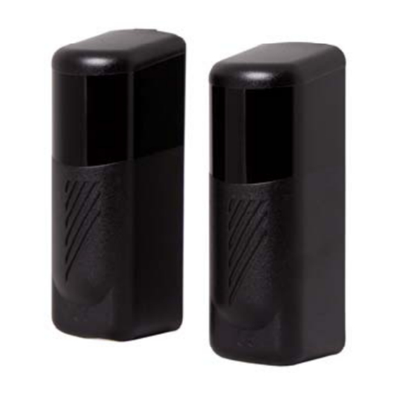
Page 6: Photoelectric Barrier Ls18
Installation and operating instructions Photoelectric barrier LS18 Photoelectric barrier LS18 Range of application Photoelectric barrier with transmitter and receiver to secure gates and barrier systems. Dimensions Drawing 2 Technical data Power supply 12 – 24Vac/dc, adjustable by plug-in jumpers Power input transmitter... -
Page 7: Electrical Connections And Adjustments
Installation and operating instructions Photoelectric barrier LS18 Electrical connections and adjustments 3.4.1 Transmitter Drawing 3 Electrical connections of transmitter: - 12/24Vac/dc + 12Vdc + 12/24Vac/dc Table 2 DIP-switch: Function DIP 1 = ON Synchronisation activated 12/24V DIP 1 = OFF... -
Page 8: Receiver
Installation and operating instructions Photoelectric barrier LS18 3.4.2 Receiver Drawing 4 Electrical connections of receiver: - 12/24Vac/dc (see also Jumper J1) + 12/24Vac/dc (see also Jumper J2) Tabelle 4 DIP-switch: Function DIP 1 = ON Synchronisation activated 12/24V DIP 1 = OFF... -
Page 9: Connection Example And Synchronisation
Installation and operating instructions Photoelectric barrier LS18 Jumper J1 / J2: 12Vac/dc 24Vac/dc Relay contact NC Relay contact NO Table 6 LED-display: The LED lights up when the photoelectric barrier is aligned correctly and there is no obstacle between transmitter and receiver. -
Page 10: Installation Und Alignment
Installation and operating instructions Photoelectric barrier LS18 Installation und alignment Drawing6 Open the photoelectric barrier with a lever, e.g. a screwdriver, at the bottom of the housing. Drawing7 Base part Tapping screw Drills for cable entry Circuit board Support Pan lock... -
Page 11: Functional Test
Installation and operating instructions Photoelectric barrier LS18 Functional test Under unfavourable conditions like rain or fog as well as a poor alignment of the photoelectric barrier, the range of the photoelectric barrier may be sharply reduced. The supplied filter (foil) is used to simulate these unfavourable conditions. - Page 12 Installation and operating instructions Photoelectric barrier LS18 Index C P Connection example ........8 Power supply ..........5 D R Declaration of conformity ......4 Range of application ........5 Degree of protection ........5 Receiver ............7 Dimensions ..........5 S ...
Need help?
Do you have a question about the LS18 and is the answer not in the manual?
Questions and answers