Advertisement
Quick Links
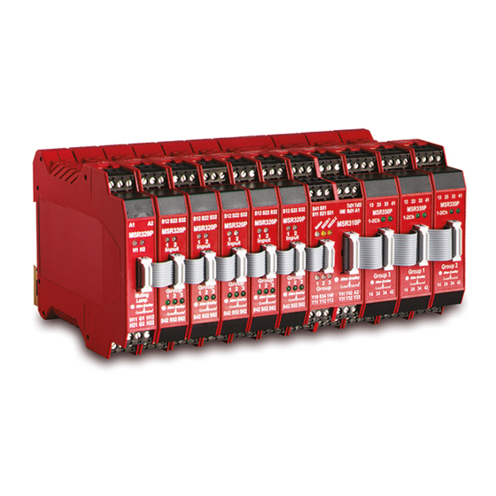
MSR300 Modular Safety Control System
Summarized Table of Contents
Topic
-
Detailed Table of Contents
1
Important User Information
2
About This Manual
3
MSR300 System: Product and Applications Overview
4
MSR300 Modules: Details
5
Special Functions: Robot Safety and Combination Logic
6
Faults / Errors: Detection and Response
7
Installation, Start-Up, Operation, Maintenance
8
Application Examples
9
Serial Data Communication Protocols
Annexure
Rockwell Automation
MSR300 Safety System Manual
Instruction Manual
MSR300 Manual.doc
Page
2
4
6
8
20
41
49
52
59
69
84
Pg 1 of 85
Advertisement

Subscribe to Our Youtube Channel
Related Manuals for Rockwell Automation MSR300


Summary of Contents for Rockwell Automation MSR300
- Page 1 Topic Page Detailed Table of Contents Important User Information About This Manual MSR300 System: Product and Applications Overview MSR300 Modules: Details Special Functions: Robot Safety and Combination Logic Faults / Errors: Detection and Response Installation, Start-Up, Operation, Maintenance Application Examples...
- Page 2 1.5 Technical Support 2 About This Manual 2.1 Content Guidance 2.2 Annotation Symbols 2.3 Document Disclaimer 3 MSR300 System: Product and Applications Overview 3.1 Safety Standards and Safety Relay Functions 3.1.1 Safety Standards 3.1.1.1 EN 954 - 1 3.1.1.2 EN 61508 3.1.2 MSR300 Safety Relay Functions...
- Page 3 MSR300 Safety System Manual 4.2 MSR320 Input Module 4.2.1 Terminals 4.2.2 LED Indicators 4.2.3 Settings and Wiring 4.2.3.1 1-Channel Emergency Stop 4.2.3.2 2-Channel Emergency Stop 4.2.3.3 3-Channel Emergency Stop 4.2.3.4 Safety Mats 4.2.3.5 Safety Gate 4.2.3.6 Light Curtain 4.2.3.7 Two-hand Control 4.2.3.8 2-Channel Emergency Stop and Light Curtain...
-
Page 4: Authorized Personnel
"Standard" can mean a named / numbered industry standard, EU / IEC directive, technical statute or regulation. "Product" can refer to an MSR300 System consisting of a combination of MSR300 Series Modules or any one of these modules. Intended Product Applications The MSR300 Safety System is a modular, intelligent safety control system for monitoring •... - Page 5 MSR300 Safety System Manual Rockwell Automation MSR300 Manual.doc Pg 5 of 85...
- Page 6 [Presently only for USA and Canada. Information for other zones expected here in the near future] • The Rockwell Automation / Allen Bradley sales / customer support office nearest to you. This information is available at: http://www.rockwellautomation.com/locations/ Rockwell Automation MSR300 Manual.doc...
- Page 7 "Standard" can mean a named / numbered industry standard, EU / IEC directive, technical statute or regulation. "Product" can refer to an MSR300 System consisting of a combination of MSR300 Series Modules, or to any one of these modules. Content Guidance Chapter 1 contains preliminary user information: this must be read and understood before proceeding to Chapters 3 onward.
- Page 8 MSR300 Safety System Manual Chapter 9 has detailed information about the serial data communication protocols. Annotation Symbols The following symbols have prominently inserted at appropriate places in this document to draw the reader's attention to important points: Symbol Meaning This symbol is intended to draw the reader's attention to...
- Page 9 The safety standards relevant to this product and its application are outlined in brief in Section 3.1.2 below. General The MSR300 Safety System is intended for applications requiring safety monitoring of machinery in accordance with the following directives / standards: • EN954-1: Safety-Related Parts Of Control Systems; up to Category 4.
- Page 10 MSR300 Safety System Manual 3.1.1 Safety Standards MSR300 Series Modules conform to the Essential Health & Safety Requirements (EHSR's) of the European Machinery Directive (98/37/EC), the relevant requirements of the Low Voltage Directive (73/23/EEC as amended by 93/68 EEC) and the essential protection requirements of the EMC Directive (89/336/EEC as amended by 92/31 EEC).
- Page 11 [1/h] 3 contacts PFH(T )≈ 2,86E-11 [1/h] Standard configuration: MSR300 System consisting of: 1 MSR310, 4 MSR320, 1 MSR330, 1 MSR329 (Each MSR320 configured for two single channel inputs) )= 8,17E-09 *t T (15% PFD Test interval: 2,1 Years avSystem...
- Page 12 MSR300 Safety System Manual 3.1.2 MSR300 Safety Relay Functions MSR300 Systems can be used for various safety relay functions outlined below, when appropriately configured for the respective function. Simultaneity monitoring (sometimes referred to as synchronization monitoring or coincidence gating) is often necessary for many of these safety applications. This means that 2 (sometimes even 3) input contacts must be closed (or reset) simultaneously to clear this set of inputs (simultaneity between all channels of one input).
- Page 13 MSR300 muting does not monitor material flow but is especially designed and limited to applications as explained in the Robot cell examples later in this document (safe position monitoring of the Robot arm).
- Page 14 MSR310 Base Module. Up to six MSR330 Output Modules can be included in an MSR300 System, for a maximum of 18 N/O safety outputs plus 6 N/C auxiliary outputs. The integrity of all safety inputs are constantly checked by means of feedback of the safety loops.
- Page 15 (see setup details in Chapter 7.3). The MSR300 System is suitable for safety monitoring and control of robot cells, with or without additional safe areas. The special MSR329 Muting Lamp Module is available for this.
- Page 16 3 x 6 = 18 N/C plus 1 x 6 = 6 N/O auxiliary contacts. A minimum of one and a maximum of six Output Modules can be included in a single MSR300 System. MSR330 Output Modules are available in three versions, each specific for one of three output groups: i.e., Group 1, Group 2, Group 3, respectively.
- Page 17 MSR300 Safety System Manual MSR300 Modules: Specifications 3.4.1 MSR310 Specifications Standards IEC/EN60204-1, ISOTR12100, ISO13849-1 Approvals CE marked for all applicable directives Power supply Nominal: 24 VDC. Range: 0.8 to 1.1 x rated voltage Power consumption Reset Monitored manual and / or automatic...
- Page 18 MSR300 Safety System Manual 3.4.2 MSR320 Specifications Standards IEC/EN60204-1, ISOTR12100, ISO13849-1 Approvals CE marked for all applicable directives Power supply Nominal: 24 VDC. Range: 0.8 to 1.1 x rated voltage Power consumption approx. 3W Safety inputs 1 N/C, 2 N/C, 3 N/C, safety mat, light curtain, N/C-N/O, two-...
- Page 19 MSR300 Safety System Manual 3.4.3 MSR330 Specifications Standards IEC/EN60204-1, ISOTR12100, ISO13849-1 Approvals CE marked for all applicable directives Power supply 24 VDC from the MSR310 Base Module Power consumption 1.5 W Output fuses (external) 6 A slow blow, or 10 A quick blow.
- Page 20 MSR300 Safety System Manual 3.4.4 MSR329 Specifications Standards IEC/EN60204-1, ISOTR12100, ISO13849-1 Approvals CE marked for all applicable directives Power supply Nominal: 24 VDC. Range: 0.8 to 1.1 x rated voltage Power consumption Inputs Monitoring of 2 muting lamps, 30 mA - 200 mA each...
- Page 21 MSR300 Safety System Manual MSR300 Modules: Details MSR310 Base Module MSR310 MSR310 Internal Block Schematic Diagram Front View Functions: System control, safety and auxiliary output contacts, supervision of bus-connected input and output modules. Auxiliary outputs: 3 solid-state switch outputs for signaling the states of output groups.
-
Page 22: Led Indicators
MSR300 Safety System Manual Y40, Y41, Y42 Reset configuration Start button Y31 – Y33 Solid-state auxiliary outputs for groups 1, 2 and 3 +24V for reset circuit and feedback loops Y11 – Y13 Feedback loop inputs for Groups 1, 2 and 3 4.1.2 LED Indicators... - Page 23 MSR300 Safety System Manual 4.1.3 Settings, Connections, Start-Up Reset mode selection (reset switch connection and jumper settings): Reset button has to be installed at a place where the dangerous area can be visual monitored. Automatic reset is only allowed if the start of the...
- Page 24 MSR300 Safety System Manual 4.1.4 Auxiliary Outputs (Solid-State Switches) The MSR310 Base Module has three LEDs and three auxiliary (solid-state switch) outputs that indicate the states of the three Output Groups, respectively. Condition Group 1 active Group 1 inactive Group 2 active...
- Page 25 MSR300 Safety System Manual 4.1.5 Output Groups Feedback Every output group has its own feedback loop. This loop has to be closed for each group before the respective group can be activated. Function Wiring External device for Group 1 External device for Group 2...
- Page 26 MSR300 Safety System Manual 4.1.6 Input Fault Logging If inputs are wired for simultaneity monitoring, the following events are registered as faults and stored in EEPROM: • Simultaneity time limit is exceeded. • Not all channels change state as required if input is cycled •...
- Page 27 MSR300 Safety System Manual MSR320 Input Module MSR320 MSR320 Rotary Switches & Settings Front View (Located on right side of the module) Functions: Processing inputs from various safety sensing devices. Assignment of sensing inputs to output switching groups by means of redundant rotary coded switches: one set selects the input function, the other set selects the output group.
- Page 28 MSR300 Safety System Manual An MSR320 Input Module can be set up for any one of the following safety functions: • Logic function (Group3 = Input1 OR Input2 OR Group1) • 1-channel emergency stop • 2- channel emergency stop or 4-wire safety mat •...
- Page 29 MSR300 Safety System Manual Selecting output groups: Switch Function LED Gr 1 LED Gr 2 LED Gr 3 settings OR logic function (* Flashes (Group 3 = Input 1 OR Input 2 OR Group 1) Group 1 (*²) Group 2...
- Page 30 MSR300 Safety System Manual LED indication of Output Group assignment: The Input Module has three LEDs for indicating its assigned Output Group Module. The Input Module has two additional LEDs that give diagnostic information as follows: States Function LED Input 1...
- Page 31 MSR300 Safety System Manual For following 2- and 3 channel E-stop examples fault exclusion between wiring both e-stop circuits (Input1 and Input2). 4.2.3.2 2-Channel Emergency Stop Switch setting: 2 Without simultaneity monitoring Input 1 Input 2 Solid-state auxiliary Solid-state auxiliary...
- Page 32 MSR300 Safety System Manual 4.2.3.3 3-Channel Emergency Stop Switch setting: 3 Without simultaneity monitoring. Input 1 Input 2 Solid-state auxiliary Solid-state auxiliary output: Input 1 output: Input 2 S11-S12: N/C S11-S42: N/C Not available Not available S21-S22: N/C S21-S52: N/C...
- Page 33 MSR300 Safety System Manual 4.2.3.5 Safety Gate Switch setting: 4 or 5 Without simultaneity monitoring. Input 1 Input 2 Solid-state auxiliary Solid-state auxiliary output: Input 1 output: Input 2 S11-S12: N/C S11-S42: N/C S11-S22: N/O S11-S52: N/O With simultaneity monitoring (3 second limit).
- Page 34 MSR300 Safety System Manual 4.2.3.6 Light Curtain Switch setting: 6 Without simultaneity monitoring. Input 1 Input 2 Solid-state auxiliary Solid-state auxiliary output: Input 1 output: Input 2 OSSD1-S12 OSSD1-S42 OSSD2-S22 OSSD2-S52 4.2.3.7 Two-hand Control Switch setting: 7 With simultaneity monitoring (0.5 second limit).
- Page 35 MSR300 Safety System Manual 4.2.3.8 2-Channel Emergency Stop and Light Curtain Switch setting: 8 Without simultaneity monitoring of Input 1 and Input 2. Input 1 Input 2 Solid-state auxiliary Solid-state auxiliary output: Input 1 output: Input 2 S11-S12: N/C OSSD1-S42...
- Page 36 MSR300 Safety System Manual 4.2.3.9 Safety Gate and Light Curtain Switch setting: 9 Without simultaneity monitoring of Input 1 and Input 2. Input 1 Input 2 Solid-state auxiliary Solid-state auxiliary output: Input 1 output: Input 2 S11-S12: N/C OSSD1-S42 S11-S22: N/O...
- Page 37 MSR300 Safety System Manual MSR330 Output Module 13 23 33 41 13 23 33 41 13 23 33 41 Group 1 Group 2 Group 3 14 24 34 42 14 24 34 42 14 24 34 42 MSR330 Modules: Group 1, Group 2, Group 3 Functions: Safety contact outputs.
- Page 38 MSR300 Safety System Manual 4.3.2 LED Indicators Function / Diagnostics Ch 1 Ch 2 Relay 1 on Green Relay 1 off Relay 2 on Green Relay 2 off MSR329 Muting Lamp Module MSR329 MSR329 Connections Front View Functions: Connection and control of muting lamps.
- Page 39 These provide area position feedback to the MSR300 system in order to ignore e.g. safety light curtains as long as the robot arm is not working in the near of the light curtain protected area.
- Page 40 MSR300 Safety System Manual 4.4.2 LED Indicators Function / Diagnostics Muting lamp 1 off Muting lamp 1 on Green Muting lamp 1 faulty, but reserve lamp 1 OK Muting lamp 1 and reserve lamp 1 faulty Flashes red Muting lamp 2 off...
- Page 41 Robot Safety Control 5.1.1 General Robot safety control is a special function for which an MSR300 System can be set up. This function makes it possible to continuously verify that a robot arm is always within its specified safe operating zone, typically demarcated by light curtain type safety sensors in combination with special cam-switches fitted on robot rotating turrets or arms.
- Page 42 1 or Group 2 Output assigned to it. (Note: Output Module Group 1 and 2 not physically necessary ) • An MSR300 System cannot have a Robot Module (Input Module set up for robot function) and a Logic Module (Input Module set up for logic function): i.e., the system can have either one or the other type of module, not both.
- Page 43 MSR300 Safety System Manual • One MSR300 System cannot have more than one Additional Safe Area Module (Input Module set up for additional safe area function). • An MSR300 System cannot have an Additional Safe Area Module (Input Module set up for additional safe are function) and a Logic Module (Input Module set up for logic function): i.e., the system can have either one or the other type of module, not...
- Page 44 MSR300 Safety System Manual Special Logic Functions An MSR300 System can be configured for applying OR logic to a combination of inputs of one or more Input Modules. This allows e.g. limited access to dangerous areas by use of 3-position enabling switches or enabling pendants (see application examples below).
- Page 45 MSR300 Safety System Manual Example 1 Door closed > = & Output Pendant enable Group 3 Hydraulic power Hydraulic power Door closed Pendant enable Group 3 Group 1 Logic function 2-channel Safety gate 2-channel Logic function: Switch setting: 0 Group 1:...
- Page 46 MSR300 Safety System Manual Example 2 Door closed & Group1 > = Light curtain clear & Pendant enable Output Group3 CNC E-stop & Output Group2 CNC E-stop Door closed Pendant enable Light curtain Group2 + 3 Group 1 + 2...
- Page 47 MSR300 Safety System Manual Example 3 Pendant enable 1 Door closed & > = Light curtain clear & Pendant enable 2 Output Group 3 CNC E-stop & Output Group 2 CNC E-stop Door closed Pendant enable Light curtain Group2 + 3...
- Page 48 MSR300 Safety System Manual Example 4 (Zoning application without OR-logic function) Front gate & CNC E-stop Output Group 1 Door closed Light curtain clear & Output Group 2 CNC E-stop Door closed Front gate Light curtain Group 1 + 2...
- Page 49 [Note: In the following part of this document, "fault" can mean the occurrence of an internal failure or defect, an external wiring or signal error, or a system configuration error]. The MSR300 System has extensive error detection capabilities. Faults, symptoms and corrective action are categorized and described below. Major Faults Major faults are indicated by the "Status"...
- Page 50 MSR300 Safety System Manual Recoverable Faults During Start-Up or Operation Recoverable faults are also indicated by the "Status" LED, but by different flashing patterns. The various recoverable faults and their corresponding LED flashing patterns are described below. Note: Shut down power before corrective action (except Input switch fault). After modification of configuration the set-up procedure as described in the next chapter is required.
- Page 51 MSR300 Safety System Manual Recoverable Configuration Faults During Start-Up or Operation Recoverable configuration faults are also indicated by the "Status" LED, but by different flashing patterns. The various configuration faults and their corresponding LED flashing patterns are described below. Note: Shut down power before corrective action. After modification of configuration the set-up procedure as described in the next chapter is required.
- Page 52 MSR300 Safety System Manual Installation, Start-Up, Operation, Maintenance Safety Precautions and Practices Use this product only for intended applications: The MSR300 Safety System is intended for applications requiring safety monitoring of machinery in accordance with the following directives / standards: •...
- Page 53 MSR300 Safety System Manual Observe electrical safety regulations and good practices: Electrical safety regulations stipulated by the appropriate technical authorities must be observed. Do not use if the product is damaged or diminished in any way: Carefully inspect each module before it is installed (or re-installed).
- Page 54 MSR300 Safety System Manual Installation 7.2.1 Environmental Considerations MSR300 Series Modules must be installed inside protected control panels / cabinets appropriate for the environmental conditions of the industrial location. The protection class of the panel / cabinet should preferably be IP 54 or higher.
- Page 55 MSR300 Safety System Manual 7.2.2 Mechanical Dimensions: Side view and dimensions: Modules widths: all MSR300 Modules MSR310 = 35 mm / 1.78 in. MSR320 = 17.5 mm / 0.69 in. MSR329 = 17.5 mm / 0.69 in. MSR330 = 22.5 mm / 0.89 in.
- Page 56 MSR300 Safety System Manual Vibration and mechanical shock: The MSR300 modules must not be subjected to vibration or mechanical in excess of the specified limits (in accordance with IEC 68 part: 2-6/7): Vibration: 10 – 55 Hz, 0.35 mm Mechanical shock: 10g, 16 msec, 100 shocks 7.2.3 Electrical...
- Page 57 MSR300 Safety System Manual Set-Up After the MSR300 System has been assembled, it must be programmed with information about the system modules configuration. This data is stored in non-volatile memory and compared with the configuration detected each time the system is switched on. Any difference between the freshly detected configuration and the programmed configuration is interpreted as an error condition.
-
Page 58: Operation
MSR300 Safety System Manual Operation Once an MSR300 System is correctly set up, it starts and operates automatically in accordance with the settings done: it needs no operator attention or action during its normal operation Maintenance An MSR300 System that is correctly configured, set up and installed is inherently maintenance-free. -
Page 59: Application Examples
MSR300 Safety System Manual Application Examples Some application examples are presented in this chapter to assist the understanding and usage of this product. The over-all safety system, external devices, and external electrical circuits will have to designed / selected / configured depending on the unique requirements of each application. - Page 60 MSR300 Safety System Manual Robot Cell, 2 areas (Input 1 OR Group 1) AND (Input 2 OR Group 2) = Group 3 (muting with cross control) Muting Muting lamp 2 lamp 1 0° Restricted space 270° 90° Station Station Danger zone 2 Danger zone 1 90°...
- Page 61 MSR300 Safety System Manual Robot Cell, 2 areas (Input 1 OR Group 1) AND (Input 2 OR Group 2) = Group 3 (muting with cross control) Muting Muting lamp 2 lamp 1 0° Restricted space Muting 270° 90° Station Station...
- Page 62 MSR300 Safety System Manual Robot Cell, 2 areas (Input 1 OR Group 1) AND (Input 2 OR Group 2) = Group 3 (muting with cross control) Muting Muting lamp 2 lamp 1 0° Restricted space Muting 90° 270° Station Station...
- Page 63 MSR300 Safety System Manual Robot Cell, 2 areas (Input 1 OR Group 1) AND (Input 2 OR Group 2) = Group 3 (muting with cross control) Muting Muting lamp 2 lamp 1 0° Restricted space No muting 90° 270° Station...
- Page 64 MSR300 Safety System Manual Robot Cell, 2 areas (Input 1 OR Group 1) AND (Input 2 OR Group 2) = Group 3 (muting with cross control) Muting Muting lamp 2 lamp 1 0° Restricted space 90° 270° Station Station No muting...
- Page 65 MSR300 Safety System Manual Robot cell, 2 areas Modules and I/O configuration MSR300 System configuration: Input 1 Input 2 ”1” ”0” MSR310 Base Module – 1 MSR320 Input Modules – 3 MSR330 Output Module – 1 MSR329 Muting Lamp Module – 1...
- Page 66 MSR300 Safety System Manual Robot Cell 3 Areas Muting Muting 0° lamp lamp Pos 2 On if in safe area Additional safe area 270° 90° Station Station Restricted Restricted space space Pos 1 Danger zone 2 Danger zone 1 90° area 270°...
- Page 67 MSR300 Safety System Manual Robot cell 3 areas Modules and I/O configuration Muting Muting 0 degrees lamp lamp Additional Operator Operator safe area Load Station 1 Load Station 2 Light curtain Light curtain muted active Restricted Restricted space space 270°...
- Page 68 MSR300 Safety System Manual Robot cell, 3 areas Modules and I/O configuration: external device linkages Module Configuration Muting Lamp Control = 2 Lamps + 2 Reserve Lamps Input Module 1 Group selection 1, Function 8 Input Module 2 Group selection 2, Function 8...
- Page 69 MSR300 Safety System Manual Serial Data Communication: Details The MSR310 is equipped with two RS232 serial data interfaces: one can be used in bi- directional, the other in uni-directional mode. Serial Data Interface Connections The serial interface connections are illustrated below.
- Page 70 MSR300 Safety System Manual Read Multiple Registers (0x03) Query: Fieldname Example Slave Address 0x01 Function Code 0x03 Start Address (High byte) 0x00 Start Address (Low byte) 0x02 Number of registers (High byte) 0x00 Number of registers (Low byte) 0x02 CRC (High byte)
- Page 71 MSR300 Safety System Manual Write Single Registers (0x06) Query: Fieldname Example Slave Address 0x01 Function Code 0x06 Start Address (High byte) 0x00 Start Address (Low byte) 0x03 Data (High byte) 0x00 Data (Low byte) 0x02 CRC (High byte) 0xF8 CRC (Low byte)
- Page 72 MSR300 Safety System Manual 9.2.2 MSR310 Parameters Para- Name Size Value Address meter Device status 2 bytes 0x0000 – 0xFFFF 0x0000 Input status 1 2 bytes 0x0000 – 0xFFFF 0x0001 Input status 2 2 bytes 0x0000 – 0xFFFF 0x0002 Configuration status EM 1 2 bytes 0x0000 –...
- Page 73 MSR300 Safety System Manual Low Byte: Function Fault Cross loop Group 3 interrupted Group 2 interrupted Group 1 interrupted Group 3 EDM Loop closed Group 2 EDM Loop closed Group 1 EDM Loop closed Input status 1 (Parameter 2: states of safety inputs)
- Page 74 MSR300 Safety System Manual Low Byte: Function Reserved Fault: Different switch settings of input modules between the two channels Fault: Invalid configuration of extension modules Fault: Reserve Muting lamp 2 Fault: Muting lamp 2 Fault: Reserve Muting lamp 1 Fault: Muting lamp 1 Fault: at least one Input (lock-out-release, no synchrony activity) Configuration status (Parameters 4 ...
- Page 75 MSR300 Safety System Manual Low Byte: Function Input error monitoring, extension module 4, input 2 Input error monitoring, extension module 4, input 1 Input error monitoring, extension module 3, input 2 Input error monitoring, extension module 3, input 1 Input error monitoring, extension module 2, input 2...
- Page 76 MSR300 Safety System Manual Low Byte Function Faulty input switch, extension module 4, input 2 Faulty input switch, extension module 4, input 1 Faulty input switch, extension module 3, input 2 Faulty input switch, extension module 3, input 1 Faulty input switch, extension module 2, input 2...
- Page 77 MSR300 Safety System Manual RS232 Unidirectional Baud rate: 4800 Circle time: Data transmission without query Byte Name Function Value Start byte 0x02 Device status Bit 7 + Bit 6: 0x00 … 0xFF 00 = Jumper Y40 – Y41–Y42 01 = Jumper Y40 - Y41...
- Page 78 MSR300 Safety System Manual Input status 3 Bit 7: reserved 0x00 … 0x0F Bit 6: reserved Bit 5: reserved Bit 4: reserved Bit 3: Extension module 10 Input 2 interrupted Bit 2: Extension module 10 Input 1 interrupted Bit 1: Extension module 9 Input 2 interrupted...
- Page 79 MSR300 Safety System Manual Split bytes: Byte Name Function Value Configuration 1 Version number / Number of extension modules Configuration 2 Switch settings extension module 1 Configuration 3 Switch settings extension module 2 Configuration 4 Switch settings extension module 3...
- Page 80 MSR300 Safety System Manual CRC Generation (Code Examples) CRC Calculation Basics The CRC calculation is started by first preloading a 16-bit register to all 1’s. Then a process begins of applying successive eight-bit bytes of the message to the current contents of the register.
- Page 81 MSR300 Safety System Manual Example 1: The following example calculates the CRC using the method described earlier. Note: This function performs the swapping of the high/low CRC bytes internally. Therefore the CRC value returned from the function can be directly placed into the message for transmission.
- Page 82 MSR300 Safety System Manual Example 2 This example uses another approach to calculate the CRC; All of the possible CRC values are pre-loaded into two arrays, which are simply indexed as the function increments through the message buffer. One array contains all of the 256 possible CRC values for the high byte of the 16-bit CRC field, and the other array contains all of the values for the low byte.
- Page 83 MSR300 Safety System Manual 0x00, 0xC1, 0x81, 0x40, 0x01, 0xC0, 0x80, 0x41, 0x00, 0xC1, 0x81, 0x40, 0x00, 0xC1, 0x81, 0x40, 0x01, 0xC0, 0x80, 0x41, 0x01, 0xC0, 0x80, 0x41, 0x00, 0xC1, 0x81, 0x40, 0x00, 0xC1, 0x81, 0x40, 0x01, 0xC0, 0x80, 0x41,...
-
Page 84: Warranty
Seller. 1. Warranty (a). Allen-Bradley / Rockwell Automation Hardware: Seller warrants that new hardware Products furnished hereunder will be free from defects in material, workmanship and design for a period of one (1) year from the date of invoice from Seller or its appointed distributor, as the case may be. - Page 85 MSR300 Safety System Manual limitations) extend to buyer’s customers if buyer is a seller-appointed distributor for the products. 2. Disclaimer And Limitation Of Liability To the fullest extent permitted by applicable law, seller will not be liable for any business...
Need help?
Do you have a question about the MSR300 and is the answer not in the manual?
Questions and answers