Advertisement
Quick Links
EN
Read the safety instructions before starting the installation.
DE
Lesen Sie die Sicherheitshinweise, bevor Sie mit der Installation beginnen.
FR
Lisez les instructions de sécurité avant de commencer l'installation.
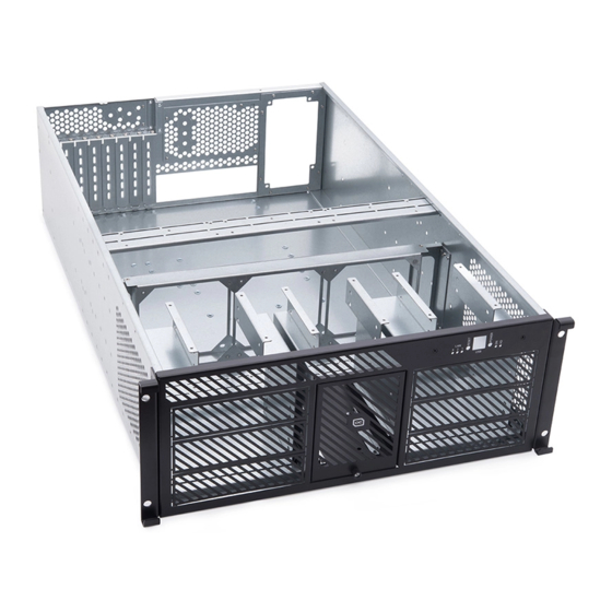
TECHNICAL DATA
EN
Hardware:
•
6x 5 1/4 inch drives
•
6x 2.5 inch HDD / SSD
•
3x 3 1/2 inch HDD split with pump
•
3x 120mm fans
•
Full motherboard support
•
2 ATX power supplies
•
1x Hot Plug power supply
•
Support for 4x 1.6 inch add on cards.
Water cooling:
•
360mm radiators
•
Pump slot for:
• ES Reservoir 1U - DDC Version
• ES Reservoir 2U - DDC Version
• Eisstation VPP
• Eisstation DDC
• Eisstation DC-LT, Laing DDC
•
Mounting for Distroplate C1
•
Mounting for Distroplate C2
•
Mounting for Distroplate C3
•
Mounting for Distroplate C5
•
Bulkhead fitting
Slide rail for easy insertion into the rack.
ALPHACOOL ES 4U - 19 - SERVERRACK -
TECHNISCHE DATEN
DE
Hardware:
•
6x 5 1/4 Zoll Laufwerke
•
6x 2,5 Zoll HDD / SSD
•
3x 3 1/2 Zoll HDD geteilt mit Pumpe
•
3x 120mm Lüfter
•
Volle Mainboard Unterstützung
•
2 ATX Netzteile
•
1x Hot Plug Netzteil
•
Unterstützung für 4x 1,6 Zoll
Erweiterungskarten.
Wasserkühlung:
•
360mm Radiatoren
•
Pumpeneinschub für:
• ES Reservoir 1U - DDC Version
• ES Reservoir 2U - DDC Version
• Eisstation VPP
• Eisstation DDC
• Eisstation DC-LT, Laing DDC
•
Halterung für Distroplate C1
•
Montage für Distroplate C2
•
Montage für Distroplate C3
•
Montage für Distroplate C5
•
Schottverschraubung
Gleitschiene für einfaches einschieben in
das Rack.
WATERCOOLING READY
DONNÉES TECHNIQUES
FR
Le hardware :
•
Lecteurs 6x 5 1/4 pouces
•
6x 2,5 pouces HDD / SSD
•
3x 3 1/2 pouces HDD split avec pompe
•
3x ventilateurs de 120mm
•
Support complet de la carte mère
•
2 alimentations ATX
•
1x alimentation Hot Plug
•
Prise en charge des cartes d'extension
de 4x 1,6 pouces.
Refroidissement par eau :
•
Radiateurs 360mm
•
Emplacement pour pompe :
• ES Reservoir 1U - DDC Version
• ES Reservoir 2U - DDC Version
• Eisstation VPP
• Eisstation DDC
• Eisstation DC-LT, Laing DDC
•
Support pour Distroplate C1
•
Montage pour Distroplate C2
•
Montage pour Distroplate C3
•
Montage pour Distroplate C5
•
Raccord de cloison.
Rail coulissant à vis de cloisonnement pour
faciliter le glissement dans le rack.
!
!
!
Advertisement

Subscribe to Our Youtube Channel
Related Manuals for Alphacool ES 4U


Summary of Contents for Alphacool ES 4U
- Page 1 ALPHACOOL ES 4U - 19 - SERVERRACK - WATERCOOLING READY Read the safety instructions before starting the installation. Lesen Sie die Sicherheitshinweise, bevor Sie mit der Installation beginnen. Lisez les instructions de sécurité avant de commencer l‘installation. TECHNICAL DATA TECHNISCHE DATEN DONNÉES TECHNIQUES...
- Page 2 Zusatzkarten einen Schock verspürt. toute procédure décrite dans le présent •Wear an antistatic smock or robe to Alphacool International GmbH empfiehlt die document ou lors de la maintenance d'un cover any clothing that may generate an folgenden Schritte bei der Durchführung aller système informatique - le cas échéant, toute...
- Page 3 electronic equipment on the outside of •Trennen Sie alle Stromkabel und - de la carte du serveur avant d'effectuer protective packaging. leitungen ab, bevor Sie das Trennchassis toute intégration ou service. öffnen Screwing components: Do not use an •Touchez toutes les surfaces métalliques automatic screwdriver such as an ACCU •Schalten Sie das Computer Modul aus non peintes du châssis avant d'effectuer...
- Page 4 SIZE IN MM MAßE IN MM MENSURE EN MM DISMANTLE / ASSEMBLE HINTERER GEHÄUSEDECKEL DÉMONTAGE / MONTAGE DU REAR HOUSING COVER DEMONTIEREN / MONTIEREN COUVERCLE ARRIÈRE DU BOÎTIER Unscrew the 6 screws in the rear cover and lift Schrauben Sie die 6 Schrauben im hinteren Dévissez les 6 vis du couvercle arrière et off the cover.
- Page 5 DISASSEMBLING / VORDERER GEHÄUSEDECKEL DÉMONTAGE / MONTAGE DU ASSEMBLING THE FRONT DEMONTIEREN / MONTIEREN COUVERCLE DU BOÎTIER AVANT HOUSING COVER Unscrew the 14 screws in the front cover and Schrauben Sie die 14 Schrauben im vorderen Dévissez les 14 vis du couvercle avant et lift off the cover.
- Page 6 Now mount your drives as shown. Use the Montieren Sie nun ihre Laufwerke wie Montez maintenant vos lecteurs comme screws supplied with the drives. dargestellt. Die entsprechenden Schrauben indiqué. Utilisez les vis fournies avec les liegen dem Lieferumfang der Laufwerke bei. lecteurs.
- Page 7 FURTHER SSD / HARD WEITEREN SSD / FESTPLATTEN POURSUITE DU MONTAGE DU SSD DISK MOUNTING. MONTAGE / DISQUE DUR Unscrew the centre knurled screw of the front Schrauben Sie die mittlere Rändelschraube Dévissez la vis à oreilles centrale du panneau panel and pull the pump insert forward as der Frontblende heraus und ziehen Sie den avant et tirez l'insert de la pompe vers l'avant...
- Page 8 Place the pump insert back into the housing. Schieben Sie den Pumpeneinschub wieder in Replacez l'insert de la pompe dans le boîtier. Next, slide the pump insert into the front panel das Gehäuse und befestigen sie ihn wieder Ensuite, faites glisser l'insert de la pompe and screw the knurled screw back on tightly.
- Page 9 Unscrew the radiator bracket by the two Entfernen Sie die beiden dargestellten Dévissez le support du radiateur par les deux screws. Schrauben um den Lüfterrahmen von der vis. Radiatorhalterung zu lösen. Next, screw the fans to the short frame as Verwenden Sie die Lüfterschrauben um die Ensuite, vissez les ventilateurs sur le cadre shown.
- Page 10 Reassemble the two holder frames and screw Montieren Sie den Lüfterrahmen, mit den Remontez les deux cadres de support et them together again with the two frame beiden dargestellten Schrauben, wieder am vissez-les à nouveau avec les deux vis du screws.
- Page 11 FRONT PANEL MOUNTING FRONTPANEL MONTAGE MONTAGE DE LA FACE AVANT Note: Hinweis: Indice: The front panel is not included and must be Das Frontpanel ist nicht im Lieferumfang Le panneau avant n'est pas inclus et doit être purchased separately. enthalten und muss separat erworben acheté...
- Page 12 Mount the controller as shown in the picture. Montieren Sie den Lüfterkontroller wie auf Montez le contrôleur comme indiqué sur la Up to 3 fan controllers can be placed and dem Bild dargestellt. Es können bis zu 3 photo. Il est possible de placer et de monter fixed.
- Page 13 MOUNTING THE PUMP MONTAGE DER PUMPE MONTAGE DE LA POMPE Note: Hinweis: Indice: Note that with large pumps there is less space Beachten Sie, dass bei großen Pumpen Notez que les grosses pompes ont moins available for the 3 1/2 inch hard drives. weniger Platz für die 3 1/2 Inch Festplatten d'espace disponible pour les disques durs de 3 zu Verfügung steht.
- Page 14 MOUNTING THE MONTAGE DER MONTAGE DE LA DISTROPLATE C2, C3, C5 DISTROPLATES C2, C3, C5 DISTROPLATE C2, C3, C5 Note: Hinweis: Indice: The Distroplates C2, C3, C5 is not included and Die Distroplates C2, C3, C5 ist nicht im La Distroplates C2, C3, C5 n'est pas incluse et must be purchased separately.
- Page 15 Mount the Distroplates C1 as shown in the Montieren Sie die Distroplate C1 wie im Bild Montez les Distroplates C1 comme indiqué picture. Up to 6 Distroplates C1 can be placed dargestellt. Die Schiene kann bis zu sechs sur la photo. Il est possible de placer et de and fixed.
- Page 16 STANDARD POWER MONTAGE D'UNE ALIMENTATION STANDARD NETZTEIL MONTAGE SUPPLY UNIT MOUNTING ÉLECTRIQUE STANDARD Mount the power supply unit as shown in the Montieren Sie das Netzteil wie im Bild Montez le bloc d'alimentation comme indiqué picture. Use the screws supplied with the dargestellt.
- Page 17 HOT PLUG POWER ENSEMBLE D'ALIMENTATION HOT PLUG NETZTEIL MONTAGE SUPPLY MOUNTING ÉLECTRIQUE HOT PLUG Unscrew the standard power supply holder by Schrauben Sie den Standard Netzteilhalter Dévissez le support de l'alimentation the four screws. an den vier Schrauben heraus. électrique standard par les quatre vis. Now mount your hot plug power supply unit.
- Page 18 MAINBOARD MOUNTING MAINBOARD MONTAGE MAINBOARD MONTAGE Check your mainboard to see which mounting Beachten Sie bitte die Positionierungen der Regardez votre carte mère pour voir quels holes are used. Marked in red in the example. Montagelöcher ihres Mainboardes (Im sont les trous de fixation utilisés. Marqué en Beispiel rot markiert) rouge dans l'exemple.
- Page 19 Insert the Rear IO shield into the housing from Klemmen Sie die Rear IO Panel- Bende von Insérez la lunette arrière du panneau IO dans the inside. innen in das Gehäuse ein. le boîtier par l'intérieur. Screw the mainboard to the spacers Montieren sie das Mainboard auf den Vissez la carte mère aux entretoises en according to their mounting holes.
- Page 20 Cut out the round panels you need as shown. Schneiden Sie die benötigen runden Blenden Découpez les ouvertures rondes requises wie dargestellt heraus. comme indiqué. Now screw in the bulkhead fitting on each Montieren sie die optional erhältlichen Maintenant, vissez la cloison en vous ajustant other's sides.
-
Page 21: Montage
MOUNTING MONTAGE MONTAGE Front Vorne La face Screw the slide rail into the rack as shown in Schrauben Sie die Gleitschiene wie im Bild Vissez la glissière dans le support comme the picture. dargestellt in das Rack ein. indiqué sur la photo. Slide the server into the rack as shown above Schieben Sie den Server wie oben Faites glisser le serveur dans le rack comme... - Page 22 V.1.00-02.2021 Alphacool International GmbH Marienberger Str. 1 D-38122 Braunschweig Support: +49 (0) 531 28874 - 0 Fax: +49 (0) 531 28874 - 22 E-Mail: info@alphacool.com General Managers: Andreas Rudnicki, Nathanael Draht, Fabian Noelte WEEE-Reg.-Nr.: DE 544444 Trade Register: Amtsgericht Braunschweig HRB 202390 VAT.ID.Nr.: DE27058421...
Need help?
Do you have a question about the ES 4U and is the answer not in the manual?
Questions and answers