
Subscribe to Our Youtube Channel
Related Manuals for EnerSys Alpha GMT 125 Series


Summary of Contents for EnerSys Alpha GMT 125 Series
- Page 1 GMT 125 Series - 15A/15B ™ 1RU Fuse Panel For Telecom Broadband Technical Manual Effective: January 2020...
- Page 2 Safety Notes Alpha Technologies Services, Inc. considers customer safety and satisfaction its most important priority. To reduce the risk of injury or death and to ensure continual safe operation of this product, certain information is presented differently in this manual. Alpha tries to adhere to ANSI Z535 and encourages special attention and care to information presented in ®...
- Page 3 GMT 125 Series - 15A/15B ™ 1RU Fuse Panel For Telecom Broadband Technical Manual C048-783-30 R01, Rev. B Effective: January 2020 © 2020 by Alpha Technologies Services, Inc. Disclaimer Images contained in this manual are for illustrative purposes only. These images may not match your installation. Operator is cautioned to review the drawings and illustrations contained in this manual before proceeding.
-
Page 4: Table Of Contents
Contents 1.0 Purpose and Applicability � � � � � � � � � � � � � � � � � � � � � � � � � � � � � � � � � � � � � � � � � � � � � � � � � � � � � � 1�1 Product Model �... -
Page 5: Purpose And Applicability
1.0 Purpose and Applicability Purpose and Applicability The purpose of this document is to detail the installation and operation instructions for the GMT 125 -15/15 Fuse Panel� 1.1 Product Model Product Model This document applies to the following models of the Alpha GMT 125 - 15/15 Fuse Panel: Table 1. -
Page 6: Unpacking And Inspection
3.0 Unpacking and Inspection Unpacking and Inspection The Alpha GMT 125 - 15/15 Series Fuse Panel was carefully packaged at the factory to withstand the normal rigors ® of shipping. However, you should carefully inspect the box and contents to confirm that no damage has occurred in transit. -
Page 7: 4�2 Mounting
4.2 Mounting Mounting NOTICE: THIS PRODUCT MUST BE INSTALLED WITHIN A RESTRICTED ACCESS LOCATION WHERE ACCESS IS THROUGH THE USE OF A TOOL, LOCK AND KEY, OR OTHER MEANS OF SECURITY, AND IS CONTROLLED BY THE AUTHORITY RESPONSIBLE FOR THE LOCATION� THIS PRODUCT MUST BE INSTALLED AND MAINTAINED ONLY BY QUALIFIED TECHNICIANS�... -
Page 8: (C016-750-278-10 Kit; Connectorized Output Models Only)
4.2.2 4.2.2 Optional Rear Rack Support Kit Optional Rear Rack Support Kit (750-278-10 Kit; Connectorized Output Models Only) (750-278-10 Kit; Connectorized Output Models Only) An optional rear rack support kit is available for GMT 125 15/15 models with connectorized outputs� This kit provides additional support to the rear of the panel by attaching to the rear of the equipment rack�... -
Page 9: 4�3 Chassis Ground
4.3 Chassis Ground Chassis Ground CAUTION! DO NOT ENERGIZE THE PANEL BEFORE CHASSIS GROUND IS CONNECTED� The chassis ground is located in the side of the panel� A two hole lug landing position is provided� See table below for termination information�... -
Page 10: 4�4 Input Connections
4.4 Input Connections Input Connections WARNING! ELECTRICAL HAZARD INPUTS MUST BE PROTECTED BY A LISTED CIRCUIT BREAKER OR BRANCH RATED FUSE� THE CIRCUIT BREAKER OR FUSE MUST BE RATED 125A MAX� MULTIPLE POWER SOURCES ARE PRESENT, ENSURE ALL INPUT POWER FEEDS ARE NOT ENERGIZED BEFORE INSTALLING THEM�... -
Page 11: 4�5 Output Connections
4.5 Output Connections Output Connections CAUTION! DO NOT PERFORM THIS STEP ON CIRCUITS WITH FUSES INSTALLED� ENSURE NO POWER IS PRESENT ON THE CIRCUIT BEING WIRED BEFORE PROCEEDING� MAKE SURE THAT ALL CABLES HAVE INSULATED TERMINALS OR HEAT SHRINK APPLIED PRIOR TO TERMINATION, AND THAT NO-OXIDE COMPOUND IS APPLIED TO ALL COPPER-TO-COPPER CONNECTIONS�... -
Page 12: 4�5�2 Connectorized Output Versions
4.5.2 4.5.2 Connectorized Output Versions Connectorized Output Versions There are 30 positive latching DC connector positions for the output circuits found on the GMT 125 -15/15 (15 per side)� Cable whips are available in a variety of lengths and wire gauges (refer to Appendix E on Page 22 for more information)�... -
Page 13: (C016-2102-10 And C016-2106-10 Models Only)
4.8 Installing the Network Cable Installing the Network Cable (C016-2102-10 and C016-2106-10 Models Only) (C016-2102-10 and C016-2106-10 Models Only) An ethernet module is available on models with per-channel current monitoring� If remote monitoring over the network is required, complete the following steps to connect the Ethernet module with embedded web server�... -
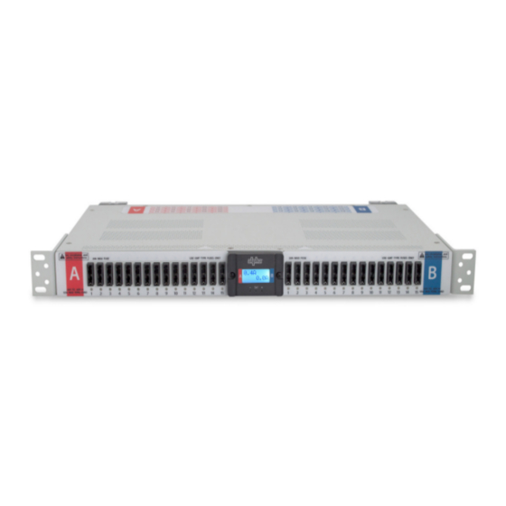
Page 14: Operation
5.0 Operation Operation 5.1 Meter Module Meter Module The GMT 125 - 15/15 fuse panel is available with an LCD meter module that displays bus current, total bus load, and an exclamation mark indication when a major alarm occurs� Screen contrast can be adjusted from 0-100 (increments of 5)� 5.2 Review System Status via the Review System Status via the Embedded Web Server... -
Page 15: 5�2�2 Real-Time Status
5.2.2 5.2.2 Real-time Status Real-time Status Upon loading the GMT 125 - 15/15 web server, the real-time status will be displayed� Site Information User can configure these settings under Administration --> Site Settings� y Site name y Site location Bus Detail y Voltage y Feeder fuse size y Load... - Page 16 Site Settings Configure Site Settings y Site name y Site location Panel Settings Configure Panel Settings y Global alarm threshold % y 40-100 y Voltage Calibration Offset y Offset can be applied in increments of +/- 3.0V to raise or lower the displayed A/B bus voltages.
-
Page 17: Product Specifications
6.0 Product Specifications Product Specifications Table 6. GMT 125 - 15/15 Model Specifications ALL MODELS Type of Input Dual Input (A/B) Circuits Input Voltage (+/- 0%) -42 to -60V DC Input Current 125A Max Maximum Input Interruption Device 150A Maximum Fuse Size 20A GMT Maximum Per Circuit Current Maximum Continuous Load on 15-20A GMT Fuses 70% Fuse Rating Maximum Continuous Load on <15A GMT Fuses... -
Page 18: Appendix A: Mechanical Drawings
Appendix A: Appendix A: Mechanical Drawings Mechanical Drawings C048-783-30 R01, Rev. B (01/2020) - Page 19 C048-783-30 R01, Rev. B (01/2020)
- Page 20 C048-783-30 R01, Rev. B (01/2020)
-
Page 21: Appendix B: Accessories
Appendix B: Appendix B: Accessories Accessories Table 7. Panel Accessories PART NUMBER DESCRIPTION C750-278-10 Rear Rack Mounting Kit; GMT 125 Appendix C: Appendix C: Supported Lugs for Termination Supported Lugs for Termination Table 8. Input Connections WIRE GAUGE ALPHA PART MANUFACTURER MANUFACTURER CRIMP DIE REQUIRED... -
Page 22: Appendix E: Output Connections
Appendix E: Appendix E: Output Connections Output Connections E.1 Output Connector Cable Whips Output Connector Cable Whips (For Connectorized Models Only) (For Connectorized Models Only) Note: All cable assemblies are unterminated unless otherwise specified. Table 11. Output Connector Cable Whips LENGTH COLOR PART NUMBER... - Page 24 Alpha Technologies Services, Inc. | 3767 Alpha Way, Bellingham, WA 98226, USA Tel�: Toll Free North America: +1 800 322 5742 | Outside US: +1 360 647 2360 | Technical Support: +1 800 863 3364 For more information visit our website at: www�alpha�com ©...
Need help?
Do you have a question about the Alpha GMT 125 Series and is the answer not in the manual?
Questions and answers