Table of Contents
Advertisement
Advertisement
Table of Contents

Related Manuals for SecuControl FTL

Summary of Contents for SecuControl FTL
- Page 1 FTL Test Blocks Reference Handbook FTL-reference-en v.181...
- Page 2 This information is printed on the front cover of this document, underneath the title. The latest release of this document can be downloaded from www.secucontrol.com/downloads. Alternatively, you may contact at any of the addresses provided on the rear cover of this document.
-
Page 3: Table Of Contents
Contents 1 Introduction The FTL Test Block ......Key Features ....... . . - Page 4 ......Covers for 19” FTL Rack Plate Cutouts ....
-
Page 5: Introduction
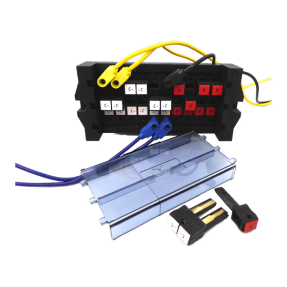
. . . ) to the voltage and current transformers and to other equipment on the system side of a power grid. The FTL Test Block uses Disconnect Pins to isolate the substation devices from the system side equipment. Once isolated, secondary injection can be performed using banana jacks on the front side of the Test Block. -
Page 6: Part Number And Manufacturing Date Location
The warranty will be void if the Test Block is disassembled (or otherwise handled inappropriately). does not assume responsibility for any damages ONTROL arising out of mishandling of our products, including test blocks that have been disas- sembled by parties other than SecuControl. -
Page 7: Principle Of Operation
2 Principle of Operation Closed Circuit In the resting state the contacts of the FTL Test Block are closed. In this situation, the signals from the system side of the installation (side A) are connected to the measuring and protection devices (side B). -
Page 9: Application
3 Application Schematic Symbols Following symbols are suggested in order to represent the FTL Test Block in schematic diagrams. Symbol Description Signal, Voltage (single pole) Current (2-pole, 4-pole) - C - - C -... -
Page 10: Typical Connection Schematic
3. A PPLICATION Typical Connection Schematic 10 004 AA... -
Page 11: Installation
4 Installation Panel Cutouts, Drilling Plans and Mounting Use the provided M5x30 screws to fix the FTL Test Block onto the panel. The screws should be tightened using a 4 mm hex drive. 8-pole Models 5.2mm 111mm 0.205in 4.370in 10-pole Models 5.2mm... - Page 12 4. I NSTALLATION 12-pole Models 5.2mm 157mm 0.205in 6.181in 14-pole Models 5.2mm 180mm 0.205in 7.087in 16-pole Models 5.2mm 203mm 0.205in 7.992in 18-pole Models 5.2mm 226mm 0.205in 8.898in...
-
Page 13: Wiring
9.803in Wiring Electrical connection terminals are located on the top and bottom of the FTL Test Block. The connection terminals combine a screw in the center with a pressure plate, accepting ring cable lugs, stripped wire or other crimp connectors. - Page 14 4. I NSTALLATION The protection equipments (current and voltage transformers, breaker, etc) should be connected to the system side terminals indicated by the even-numbers (2, 4, 6, 8, . . . ), or by the “a” suffix (1a, 2a, 3a, . . . ), depending on model.
-
Page 15: Operation
Disconnect Pins is in the testing position. This is intentional and provides a visual flag that testing is being performed. 3. For signal injection, connect the test set via the banana jacks in the FTL Test Block. This step is entirely based on your normal testing procedures, and should be planned and carefully executed by a trained technician. -
Page 17: Technical Specifications
IP20 without cover IP50 with dust cover attached FTL Test Blocks have been classified as electromagnetically benign and are therefore excluded from the scope of the European Community Directive 2004/108/EC. FTL meets or exceeds all requirements from ANSI / IEEE C37.90-2005. -
Page 18: Mechanical
6. T ECHNICAL PECIFICATIONS Mechanical # of poles Weight (kg) 1.04 1.25 1.46 1.67 1.88 2.09 2.30 (lbs) 2.29 2.76 3.22 3.22 4.14 4.61 5.07 Dimensional Drawings 8-pole Models 34mm 130mm 5.118in 1.339in 102mm 4.016in 10-pole Models 153mm 34mm 6.024in 1.339in 102mm 4.016in... - Page 19 Dimensional Drawings 12-pole Models 34mm 176mm 6.929in 1.339in 102mm 4.016in 14-pole Models 199mm 34mm 7.835in 1.339in 102mm 4.016in 16-pole Models 222mm 34mm 1.339in 8.740in 102mm 4.016in...
- Page 20 6. T ECHNICAL PECIFICATIONS 18-pole Models 34mm 245mm 9.646in 1.339in 102mm 4.016in 20-pole Models 268mm 34mm 10.551in 1.339in 102mm 4.016in...
-
Page 21: Models Available
7 Models Available Number of banana jacks The FTL test block typically comes with banana jacks both on the system side (side A) and on the device side (side B). The banana jacks on the B side constitute an essen- tial component of the test bock. -
Page 23: Accessories
This adapter is built for the connection of test equipment with relatively wide insulated banana plugs (width of 11.5 mm or more) to the FTL test block. One side of the adapter connects to the wide test lead and then connects via a short cable to a smaller banana plug that fits comfortably into the FTL banana jacks. -
Page 24: Jumper Cable
8. A CCESSORIES Jumper Cable This jumper cable allows the connection between 2 poles of the FTL test block. Both banana plugs of the jumper cable have a see-through plastic shielding that recedes when entered into the FTL banana jack. -
Page 25: Ftl 19" Rack Plates
FTL test blocks in 19” racks ONTROL that come painted in various colors and with various cutouts for FTL test blocks, in standard heights of 2U or 3U. Please contact if you require drawings ONTROL or special customizations. -
Page 26: Covers For 19" Ftl Rack Plate Cutouts
8. A CCESSORIES Special FTL Fitting Screws Fitting set to fix the FTL test block in the rack plate cutout with 3 cutouts and 30 modules. The screw set contains two M5x22 hexagon socket head cap screws (4 mm) Description Order Code Special fitting set M5... -
Page 27: Spare Parts
Order Code FTDC08 FTDC10 FTDC12 FTDC14 FTDC16 FTDC18 FTDC20 Fitting Set Fitting set to fix the FTL Test Block in the panel cutout. The screw set contains two M5x30 hexagon socket head cap screws (4 mm) and two M5 nuts. - Page 28 9. S PARE ARTS Description Order Code Fitting set M5 SCSFT...
-
Page 29: Ordering Information
10 Ordering Information Part Numbers F T L P poles config labeling Available Configurations A list of available Configurations can be found in the download section of out website. Should your application require a configuration that is not listed below, please contact at any of the addresses listed on the rear cover of this manual, or use ONTROL the configurator on our homepage. - Page 32 North America Europe South America SecuControl Inc. SecuControl GmbH SecuBrasil Ltda 2873 Duke Street Ascherslebener Str. 3 Rod Jos´ e Carlos Daux, 8600 Alexandria, VA 22314 D-06333 Hettstedt 88050-001 Florian´ o polis SC Germany Brazil Tel 1 703 838 7677...
Need help?
Do you have a question about the FTL and is the answer not in the manual?
Questions and answers