
Related Manuals for Clarke AIRMASTER 14/50P


Summary of Contents for Clarke AIRMASTER 14/50P
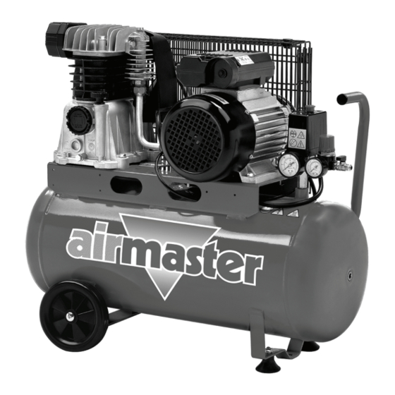
- Page 1 50L BELT DRIVEN AIR COMPRESSOR MODEL NO: AIRMASTER 14/50P PART NO: 2245306 OPERATION & MAINTENANCE INSTRUCTIONS ORIGINAL INSTRUCTIONS GC0721...
-
Page 2: Environmental Recycling Policy
INTRODUCTION Thank you for purchasing this 50L Belt Driven Air Compressor. Read this manual fully before use and follow the instructions carefully. In doing so you will ensure the safety of yourself and those around you, and you can look forward to your purchase giving you long and satisfactory service. GUARANTEE This product is guaranteed against faulty manufacture for a period of 12 months from the date of purchase. -
Page 3: Safety Precautions
SAFETY PRECAUTIONS Before using your compressor it is in your own interest to read and pay attention to the following safety precautions. 1. Compressed air is dangerous. DO NOT point a jet of air at persons or animals, and DO NOT discharge compressed air against the skin. 2. -
Page 4: Safety Symbols
SAFETY SYMBOLS Read this instruction booklet carefully before positioning, operating or adjusting the compressor. Risk of electric shock. The compressor must be disconnected from the mains supply before removing any covers. Do not use in a damp environment. Risk of accidental start-up. The compressor could start automatically in the event of a power cut and subsequent reset. -
Page 5: Electrical Connections
ELECTRICAL CONNECTIONS WARNING: READ THESE ELECTRICAL SAFETY INSTRUCTIONS THOROUGHLY BEFORE CONNECTING THE PRODUCT TO THE MAINS SUPPLY. Connect the mains lead to a standard, 230 Volt (50Hz) electrical supply through an approved 13 amp BS 1363 plug, or a suitably fused isolator switch. If the plug has to be changed because it is not suitable for your socket, or because of damage, it must be removed and a replacement fitted, following the wiring instructions shown below. -
Page 6: Attach The Wheels
ASSEMBLY CAUTION: TO PREVENT INJURY, GET ASSISTANCE WHEN LIFTING THIS COMPRESSOR. ATTACH THE WHEELS 1. Slide the axle through the wheel and hole in the wheel frame. 2. Lock the wheel in place using the washer and nut provided. 3. Fit the cap into the position shown. -
Page 7: Before Use
BEFORE USE Before connecting your compressor to the power supply, check the following:- • Push down the OFF button. • Remove the protective plastic moulding from the top of the cylinder head. • Make sure that the compressor is on level ground. •... -
Page 8: Operation
OPERATION If the compressor has not been used for more then 24 hours, open the drain valve (on the bottom of the reservoir) and drain any condensate which has collected. See page 11. MOVING THE COMPRESSOR • Stop the compressor and disconnect it from the power supply before you move it. -
Page 9: Turning The Compressor On
TURNING THE COMPRESSOR ON 1. Plug the compressor into the power supply. 2. Lift the On/Off button. • The compressor will operate until the reservoir is fully pressurised. It will then shut down. • The compressor will start up again when the pressure in the reservoir decreases. -
Page 10: Removing Tools From The Air Hose
REMOVING TOOLS FROM THE AIR HOSE WARNING: ALWAYS SET THE PRESSURE REGULATOR TO ZERO BEFORE YOU REMOVE OR REPLACE A TOOL. 1. Push down on the On/Off button to stop the compressor. 2. Turn the outlet valve handle to the off position. -
Page 11: Draining The Reservoir
DRAINING THE RESERVOIR CAUTION: YOU MUST DRAIN THE RESERVOIR AFTER EACH DAYS USE AND BEFORE YOU PUT YOUR COMPRESSOR INTO STORAGE. 1. Turn the compressor off and disconnect from the power supply. 2. Put a container below the drain valve to collect the condensate. 3. -
Page 12: Maintenance
MAINTENANCE WARNING: MAKE SURE THAT THE COMPRESSOR IS DISCONNECTED FROM THE ELECTRICAL SUPPLY BEFORE CARRYING OUT ANY MAINTENANCE DRAIN THE RESERVOIR After use, always open the drain valve to make sure that any condensate is drained off. CHECK OIL Ensure the oil level is between the min and max marks on the dipstick. See “Check the Oil level”... -
Page 13: Replacing The Oil
REPLACING THE OIL After the first 100 hours use, replace the oil using SAE30 compressor oil. Then replace the oil after every 500 hours of operation or every 6 months. To empty the oil from the machine, remove the oil drain plug from the crankcase. -
Page 14: Replacing The Drive Belt
REPLACING THE DRIVE BELT WARNING: MAKE SURE THAT THE COMPRESSOR IS DISCONNECTED FROM THE ELECTRICAL SUPPLY BEFORE REPLACING THE DRIVE BELT. 1. Rotate the clips on the front of the safety cage. 2. Remove the front of the cage and take out the worn or broken drive belt. -
Page 15: Specifications
SPECIFICATIONS MODEL AIRMASTER 14/50P Part Number 2245306 Motor Size 3 hp Voltage 230 VAC Air Displacement 394 L/min (14 cfm) Max pressure 10 Bar/145psi Receiver Capacity 50 L Ingress protection rating IP20 Fuse rating Duty cycle S3/50% Oil requirements ISO100 (SAE30) compressor oil Oil capacity 0.4L... -
Page 16: Troubleshooting
TROUBLESHOOTING CAUTION: DO NOT TRY TO REPAIR OR ADJUSTMENT IF YOU ARE UNCERTAIN. IF YOU HAVE ANY QUERIES, CONTACT YOUR CLARKE DEALER. PROBLEM PROBABLE CAUSE REMEDY The compressor Bad electrical 1. Check electrical has stopped connections. connections. and does not 2. -
Page 17: Component Parts
COMPONENT PARTS Parts & Service: 0871 410 1270 / e-mail: parts@machinemart.co.uk or customerservice@machinemart.co.uk... - Page 18 COMPONENT PARTS NO DESCRIPTION NO DESCRIPTION CRANKCASE GASKETS SET 213167002 CYLINDER PISTON RING SET CYLINDER HEAD PISTON ASSEMBLY CRANKSHAFT LOWER COVER NON RETURN VALVE VALVE HOLDER ASSEMBLY TAP BALL VALVE GASKET DRAIN.VALVE 3/8 CONROD PRESSURE REGULATOR INTAKE FILTER ASSEMBLY GAUGE 50mm 10BAR AIR COOLER GAUGE 40mm CYLINDER HEAD BOLT...
-
Page 19: Declaration Of Conformity
DECLARATION OF CONFORMITY Parts & Service: 0871 410 1270 / e-mail: parts@machinemart.co.uk or customerservice@machinemart.co.uk...
Need help?
Do you have a question about the AIRMASTER 14/50P and is the answer not in the manual?
Questions and answers