
Related Manuals for Tektronix 5B12N


Summary of Contents for Tektronix 5B12N
- Page 1 INSTRUCTION MANUAL Tektronix, Inc. • P. O. 500 • Beaverton, Oregon 97005 • Phone 644-0161 • Cables: Tektronix 1071 070-1141-00...
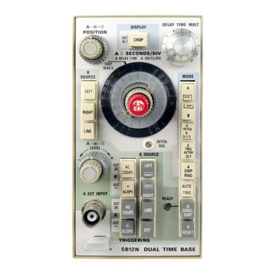
- Page 3 5B12N DELAY TIME MUll A--€-® DISPLAY POSITION SOURCE LEFT INTEN O LY' O INTEN TRIGGERING 5B12N DUAL TIME BASE...
- Page 4 Verso Filler Page...
-
Page 5: Section 1 Opera Ting Instructions
Time Base is a dual-sweep plug-in for i nt e n sifi e d segment (the use with Tektronix 5100-Series Oscilloscopes. The plug-in button must be pressed in), or it features two time-base generators, and is capable of pro permits display of the 8 Ti ducing two independent sweeps or a d el a y e d sweep. - Page 6 Operating I nstructions-5B 12N LINE: Selects line-frequency SEC O ND S/DIV switch age as the t g ge r · sign source sweep modes only). for the Time Base. B alances intensity of traces pro· IN TEN BAL duced A and time bases.
-
Page 7: General Information
NOTE Time B ase and the signal from the righ t vertical uni t is When this plug-in is used in a Tektronix 5403 oscillo displayed with th e 8 Time 8ase . For stable internal trig scope the leading edge of the no t ob... - Page 8 Instructions-5B Operating again. I n all modes, any sweep in process when the R E S E T Sweep Mode-Independent Sweep Opera button i s pressed is termina ted, allowing the system t o be tion quickly reset. The A and B buttons of the M O D E switch are Gen eral.
-
Page 9: Amplifier Mode
Operating Instructions-58 simultaneously on a tim e s h are basis established by t h e measured. Points for differential time measurement are · electronic switching circuit in the oscilloscope main selectable over the 10-division length of the A sweep, g the DE LA Y TIME MULT dial Of the fou available time slot... - Page 10 Operating nstructions-5B ---- -- --i� � sweep time � � � sweep sweep Delay t ime � Delay time � "arms" B sweep starts B sweep B sweep w ait � � for next trigger • B sweep time � •...
- Page 12 O perating I nstructions-5B 12N the A Triggering controls for a stable display. Use the Chop display mode at slower sweep rates to elim inate the Pulse to be blinking effect caused by sweep alternation. magnified 3. Push in the A I NT E N·B D L Y ' D button and position the start of the intensified zone with the D ELAY T I M E M UL T dial to the part of the display to be magnified.
-
Page 13: Performance Cond Itions
Operat i ng I n stru cti ons-5812N see Electr i c al Characteristi cs! . Measure the amou n t of hori · Example: Fig. ' ·3 sh ows a complex waveform d isplay ed on th e A sweep. The i nd icated pulse cannot be v i ewed in z o n tal m ovement, then mul t i ply th i s d i sta n c e by the B SECO N D S / D I V sw i tch setting to obtain pulse jitter in t i m e . - Page 14 Operating I n struction s - 5 8 1 2 N D E L A Y T I M E ACC U R AC Y : M A X I M U M SA F E I N P U T V O L T A G E : 3 5 0 V ( D C W i t h i n f r o m 1 JJ s/d i v 0 .
Need help?
Do you have a question about the 5B12N and is the answer not in the manual?
Questions and answers