Table of Contents
Advertisement
Quick Links
Advertisement
Table of Contents

Related Manuals for Synway SSW Series


Summary of Contents for Synway SSW Series
- Page 1 Synway SSW Series SHD-30E/60E-CT/PCI(SSW) SHD-30E/60E-CT/PCI/EC(SSW) SHD-30E/60E-CT/PCI/FAX(SSW) SHD-120E/240E-CT/PCI(SSW) SHD-120E/240E-CT/PCI/EC(SSW) SHD-120E/240E-CT/PCI/FAX(SSW) Digital Trunk Board Special-for-Switch Version 1.1 Synway Information Engineering Co., Ltd www.synway.net...
-
Page 2: Table Of Contents
1.3 Operation Principle ................... 4 Chapter 2 Installation ..............5 2.1 Hardware Structure ................... 5 2.2 System Requirements................14 2.3 Installation Procedure ................15 Appendix A Technical Specifications..........19 Appendix B Technical/sales Support..........20 Synway SSW Series E-type Digital Trunk Boards Hardware Manual (Version 1.1) Page i... -
Page 3: Copyright Declaration
Synway reserves all rights to modify this document without prior notice. Please contact Synway for the latest version of this document before placing an order. Synway has made every effort to ensure the accuracy of this document but does not guarantee the absence of errors. Moreover, Synway assumes no responsibility in obtaining permission and authorization of any third party patent, copyright or product involved in relation to the use of this document. -
Page 4: Revision History
2009-10 Initial publication Version 1.1 2010-7 Add description on the RSD043 Outlet Board. Note: Please visit our website http://www.synway.net to obtain the latest version of this document. Synway SSW Series E-type Digital Trunk Boards Hardware Manual (Version 1.1) Page iii... -
Page 5: Chapter 1 Overview
Synway Information Engineering Co., Ltd Chapter 1 Overview These Synway E-type digital trunk boards are earmarked for PBX. They have almost all functions needed for call/voice processing systems which are connected to them through E1/T1/J1 trunks. These boards are designed with the enhanced capability in echo cancellation and the DMA Read and Write function which speeds up the data transfer and minimizes the cost of CPU, further improving the system performance. -
Page 6: Features
Specialized Driver Algorithm Synway SSW Series E-type Digital Trunk Boards Hardware Manual (Version 1.1) Page 2... - Page 7 Each system supports up to 2048 channels. The complex call procedures can be analyzed and controlled through simple function calls on the driver platform, without having to understand details. Synway SSW Series E-type Digital Trunk Boards Hardware Manual (Version 1.1) Page 3...
-
Page 8: Operation Principle
Barge in DTMF/Tone Decoder Encoder Detector Detector Generator Detector Recording Playback Buffer Buffer Host Computer Interface (PCI ) Figure 1-1 Operation Principle of SSW Series E-type Boards Synway SSW Series E-type Digital Trunk Boards Hardware Manual (Version 1.1) Page 4... -
Page 9: Chapter 2 Installation
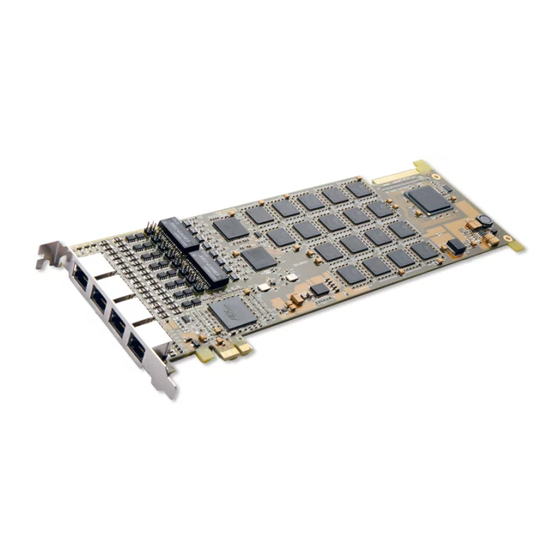
Chapter 2 Installation 2.1 Hardware Structure SHD-30E-CT/PCI(SSW) Mainboard PCI Interface Hot-swap Indicator Sync Indicator Self-defined Interface Handle with a lock Figure 2-1 Right and Front Views SHD-30E-CT/PCI/EC(SSW) Mainboard Synway SSW Series E-type Digital Trunk Boards Hardware Manual (Version 1.1) Page 5... - Page 10 Self-defined Interface Figure 2-2 Right and Front Views SHD-30E-CT/PCI/FAX(SSW) Mainboard PCI Interface Hot-swap Indicator Sync Indicator Self-defined Interface Handle with a lock Figure 2-3 Right and Front Views Synway SSW Series E-type Digital Trunk Boards Hardware Manual (Version 1.1) Page 6...
- Page 11 Self-defined Interface Figure 2-4 Right and Front Views SHD-60E-CT/PCI/EC(SSW) Mainboard PCI Interface Hot-swap Indicator Sync Indicator Handle with a lock Self-defined Interface Figure 2-5 Right and Front Views Synway SSW Series E-type Digital Trunk Boards Hardware Manual (Version 1.1) Page 7...
- Page 12 Figure 2-6 Right and Front Views SHD-120E-CT/PCI(SSW) Mainboard PCI Interface Hot-swap Indicator Sync Indicator Handle with a lock 120E Self-defined Interface Figure 2-7 Right and Front Views Synway SSW Series E-type Digital Trunk Boards Hardware Manual (Version 1.1) Page 8...
- Page 13 Figure 2-8 Right and Front Views SHD-120E-CT/PCI/FAX(SSW) Mainboard PCI Interface Hot-swap Indicator Sync Indicator Handle with a lock 120E Self-defined Interface Figure 2-9 Right and Front Views Synway SSW Series E-type Digital Trunk Boards Hardware Manual (Version 1.1) Page 9...
- Page 14 Figure 2-10 Right and Front Views SHD-240E-CT/PCI/EC(SSW), SHD-240E-CT/PCI/FAX(SSW) Mainboards PCI Interface Hot-swap Indicator Sync Indicator Handle with a lock 240E Self-defined Interface Figure 2-11 Right and Front Views Synway SSW Series E-type Digital Trunk Boards Hardware Manual (Version 1.1) Page 10...
- Page 15 Figure 2-12 Rear View RSD081 Outlet Board PCM1 OUT1 PCM2 OUT2 PCM3 OUT3 PCM4 OUT4 PCM5 OUT5 OUT6 PCM6 OUT7 PCM7 OUT8 PCM8 Figure 2-13 Front View RSD082 Outlet Board Synway SSW Series E-type Digital Trunk Boards Hardware Manual (Version 1.1) Page 11...
- Page 16 PCM3 OUT3 OUT4 PCM4 Figure 2-15 Right and Front Views RSD043 Outlet Board PCM1 PCM2 OUT1 PCM3 OUT2 OUT3 PCM4 OUT4 Figure 2-16 Right and Front Views Synway SSW Series E-type Digital Trunk Boards Hardware Manual (Version 1.1) Page 12...
- Page 17 ⑤ The RSD041 and RCU&RSD082 rear panels can work only with half-length outlet boards. Remarks: ① Here above illustrates the hardware structure of Synway E-type boards which are used exclusively for PBX. Always check the label on the back of a board to get the exact board model.
-
Page 18: System Requirements
SHD-240E-CT/PCI/FAX(SSW) 8E1/T1/J1 RSD082 4 special RJ48C Table 2-3 Board Model List 2.2 System Requirements Host System Requirements CPU: 300MHz Intel® Pentium®Ⅱ or above Memory: 256M or more Synway SSW Series E-type Digital Trunk Boards Hardware Manual (Version 1.1) Page 14... -
Page 19: Installation Procedure
Therefore, such grounding must be strictly avoided. Synway SSW Series E-type Digital Trunk Boards Hardware Manual (Version 1.1) Page 15... - Page 20 Step 2: Properly fit the required mainboard and outlet board into the Synway PBX. Insert the mainboard and outlet board into a pair of vacant slots on the Synway PBX. With the mainboard completely inserted, push the upper and bottom handles inwards at the same time until a ‘click’...
- Page 21 If you would like to construct lines for BNC or L9 conversion by yourself, you should not only make the line match the on-board interface, but also ensure the correct connection of receive and transmit lines as shown in Figure 2-18. Synway SSW Series E-type Digital Trunk Boards Hardware Manual (Version 1.1) Page 17...
- Page 22 A simple way is earthing with the third pin on the plug. No or improper grounding may cause instability in operation as well as decrease in lightning resistance. Synway SSW Series E-type Digital Trunk Boards Hardware Manual (Version 1.1) Page 18...
-
Page 23: Appendix A Technical Specifications
µ-Law 64kbps Audio Specifications IMA ADPCM 32kbps CODEC: CCITT A/µ-Law 64kbps, 13.6kbps Distortion: ≤3% 8kbps Frequency response: 300-3400Hz (±3dB) Safety Signal-to-noise ratio: ≥38dB Lightning Resistance: Level 4 Synway SSW Series E-type Digital Trunk Boards Hardware Manual (Version 1.1) Page 19... -
Page 24: Appendix B Technical/Sales Support
District, Hangzhou, P.R.China, 310053 Tel: +86-571-88860561 Fax: +86-571-88850923 Technical Support Tel: +86-571-88864579 Mobile: +86-13735549651 Email: techsupport@sanhuid.com Email: techsupport@synway.net MSN: scycindy_sh@hotmail.com Sales Department Tel: +86-571-88860561 Tel: +86-571-88864579 Fax: +86-571-88850923 Email: sales@synway.net Synway SSW Series E-type Digital Trunk Boards Hardware Manual (Version 1.1) Page 20...
Need help?
Do you have a question about the SSW Series and is the answer not in the manual?
Questions and answers