
Subscribe to Our Youtube Channel
Related Manuals for Synway TEJ100P


Summary of Contents for Synway TEJ100P
- Page 1 Synway AST Series TEJ100P/TEJ200P TEJ100E/TEJ200E TEJ101P/TEJ201P TEJ101E/TEJ201E Digital Trunk Interface Board Version 1.0 Synway Information Engineering Co., Ltd www.synway.net...
-
Page 2: Table Of Contents
Features ..........................2 Operation Principle......................3 Chapter 2 Installation ........................4 Hardware Structure ......................4 Interface Identification ......................9 Slot Compatibility........................9 System Requirements ......................10 Hardware Installation......................10 Appendix A Technical Specifications ..................13 Appendix B Technical/Sales Support ..................14 Synway TEJ100/200/101/201P, TEJ100/200/101/201E Hardware Manual (Version 1.0) Page i... -
Page 3: Copyright Declaration
Synway reserves the right to revise this manual without prior note. Please contact Synway for the latest version of this manual before placing an order. Synway has made every effort to ensure the accuracy of this manual but does not guarantee the absence of errors. Moreover, Synway assumes no responsibility in obtaining permission and authorization of any third party patent, copyright or product involved in relation to the use of this manual. -
Page 4: Revision History
Synway Information Engineering Co., Ltd Revision History Version Date Comments Version 1.0 2009-12 Initial publication. Note: Only major revisions to this manual itself recorded herein. Synway TEJ100/200/101/201P, TEJ100/200/101/201E Hardware Manual (Version 1.0) Page iii... -
Page 5: Chapter 1 Overview
TEJ201E are digital trunk interface boards which support E1, T1 and J1 environments. They are in 2U size, 120mm in length, compact in structure and high in integration. TEJ100P, TEJ200P, TEJ101P, TEJ201P include PCI bus while TEJ100E, TEJ200E, TEJ101E and TEJ201E include PCIe bus, designed especially for various application systems that require high performance. -
Page 6: Features
Figure 1-2 Application Model II: VoIP Telephony System 1.1 Features PCI/PCIe Bus Support TEJ100P/TEJ200P/TEJ101P/TEJ201P includes PCI 2.2 bus; in the universal PCI design, it supports 3.3V/5V PCI slot and PCI-X slot. TEJ100E/TEJ200E/TEJ101E/TEJ201E includes PCIe bus; supports PCI Express X1, X4, X8, X16 slots and PNP (plug and play) feature. -
Page 7: Operation Principle
Synway Information Engineering Co., Ltd Echo Cancellation The echo cancellers developed by Synway for these boards use on-board DSPs to work. TEJ101P/TEJ101E/TEJ201P/TEJ201E supports up to 128ms for time delay estimation per channel, and TEJ100P/TEJ100E/TEJ200P/TEJ200E supports 32ms, really cost-effective. It not only cancels out the effect of voice playback on DTMF and busy tones detection, but... -
Page 8: Chapter 2 Installation
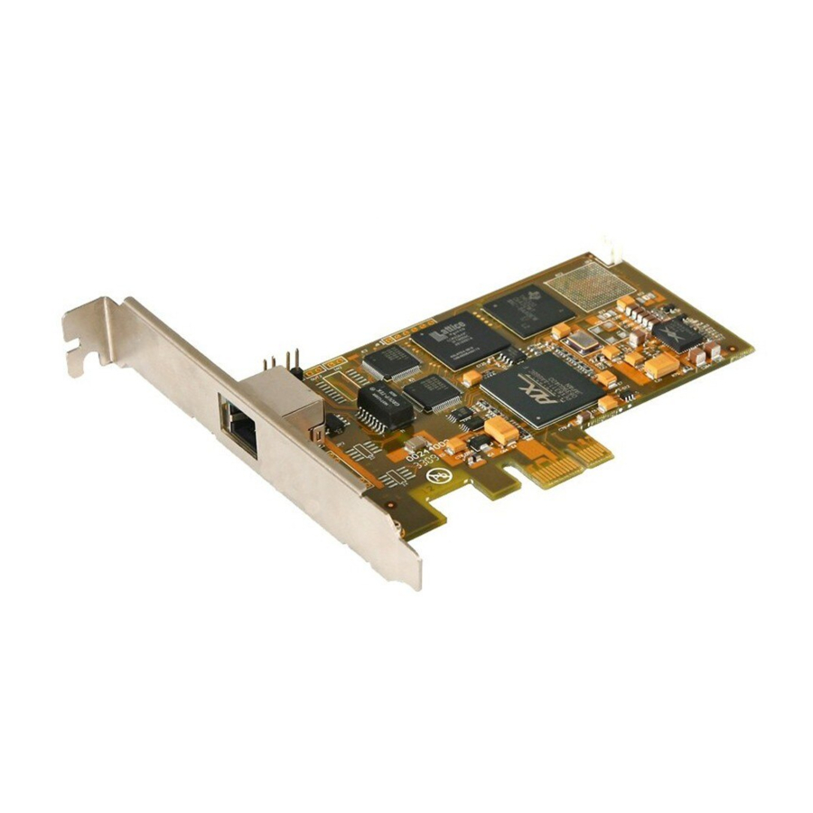
Connect to grounding jumpers at receive end RJ48C OUT1 LED1 PCM0 PCI Interface Figure 2-1 TEJ100P (Left and Front Views) Connect to grounding jumpers at receive end of PCM0 Clock Sync Interface Connect to grounding jumpers at transmit Connect to grounding... - Page 9 PCM1 jumpers at receive jumpers at transmit end of PCM1 end of PCM0 OUT1 OUT2 LED1 PCM0 LED2 PCM1 RJ48C PCI Interface Figure 2-4 TEJ201P (Left and Front Views) Synway TEJ100/200/101/201P, TEJ100/200/101/201E Hardware Manual (Version 1.0) Page 5...
- Page 10 TEJ100E, TEJ200E, TEJ101E and TEJ 201E Boards Connect to grounding jumpers at transmit end Connect to grounding Clock Sync Interface jumpers at receive end RJ48C OUT1 LED1 PCM0 PCIe Interface Figure 2-6 TEJ100E (Left and Front Views) Synway TEJ100/200/101/201P, TEJ100/200/101/201E Hardware Manual (Version 1.0) Page 6...
- Page 11 Figure 2-7 TEJ200E (Left and Front Views) Connect to grounding jumpers at transmit end Connect to grounding Clock Sync Interface jumpers at receive end RJ48C OUT1 LED1 PCM0 PCIe Interface Figure 2-8 TEJ101E (Left and Front Views) Synway TEJ100/200/101/201P, TEJ100/200/101/201E Hardware Manual (Version 1.0) Page 7...
- Page 12 LED1 and LED2 are indicators for PCM0 and PCM1. They have three states as listed below. ○ ○ ○ 1 On: PCM synchronous; 2 Flashing: PCM not synchronous; 3 Off: Port unused Synway TEJ100/200/101/201P, TEJ100/200/101/201E Hardware Manual (Version 1.0) Page 8...
-
Page 13: Interface Identification
Figure 2-11 below. S lo ts Figure 2-11 PC Slots Slot Number: 0: AGP Pro slot 1: 64-bit 5.0V PCI slot 2: 64-bit 3.3V PCI slot Synway TEJ100/200/101/201P, TEJ100/200/101/201E Hardware Manual (Version 1.0) Page 9... -
Page 14: System Requirements
6: PCI-Express x4 slot 7: PCI-Express x16 slot The TEJ100P, TEJ200P, TEJ101P and TEJ201P boards support the slots numbered 1, 2, 3 (i.e. PCI slots) in Figure 2-11; the TEJ100E, TEJ200E, TEJ101E and TEJ201E boards support the slots numbered 4, 5, 6, 7 (i.e. PCIe slots) in Figure 2-11 and the PNP (plug and play) feature. - Page 15 The on-board clock sync line is used to connect with other boards, such as digital trunk boards, analog boards from Synway or even boards from other companies, to offer a same clock to all boards connected together. This can reduce the error in faxing and guarantee the accuracy in data transmission between boards.
- Page 16 Synway Information Engineering Co., Ltd See Figure 2-13 below for the clock sync line provided by Synway. Figure 2-13 Clock Sync Line Step 6: Boot your computer and install the driver. Regarding driver installation, refer to the file ‘SynAST UserManual.doc’ for details.
-
Page 17: Appendix A Technical Specifications
120Ω balanced 8kHz interface Safety T1/J1 interface: Lightning resistance: Level 4 DSX-1 and CSU line build-outs available for different extents of signal losses, including 100Ω and 110Ω balanced Synway TEJ100/200/101/201P, TEJ100/200/101/201E Hardware Manual (Version 1.0) Page 13... -
Page 18: Appendix B Technical/Sales Support
Synway Information Engineering Co., Ltd Appendix B Technical/Sales Support Thank you for choosing Synway. Please contact us should you have any inquiry regarding our products. We shall do our best to help you. However, our technicians and salesmen are mainly responsible for maintaining our boards and providing relative technical support.
Need help?
Do you have a question about the TEJ100P and is the answer not in the manual?
Questions and answers