
Subscribe to Our Youtube Channel
Related Manuals for DEC DECrepeater 90T

Summary of Contents for DEC DECrepeater 90T
- Page 1 DECrepeater 90T Owner’s Manual Order Number EK–DETMR–OM.001 Digital Equipment Corporation...
- Page 2 The following are trademarks of Digital Equipment Corporation: DEC, DECbridge, DECconnect, DEChub, DECnet, DECserver, Digital, LAT, ThinWire, VMS, VAX, and the Digital logo.
-
Page 3: Table Of Contents
Management Managing the DECrepeater 90T ......Functions ......... . . - Page 4 Power Supply ........DECrepeater 90T ........
- Page 5 Basic Configuration Rules ......2–2 DECrepeater 90T Fault and Non-fault conditions ..4–1 Summary of DECrepeater 90 Commands .
-
Page 7: About This Manual
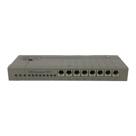
About This Manual This guide describes how to install, operate, and maintain the Digital Ethernet Twisted Pair Multiport Repeater - the DECrepeater 90T. The DECrepeater 90T is a 9-port repeater designed for standalone operation or as a managed repeater in the DEChub 90 Ethernet backplane. - Page 8 viii About This Manual Conventions Convention Meaning NOTE Provides general information. A number in a black circle in text refers to the corresponding number in an accompanying illustration. SHOW ADDRESS In text, commands are shown in all upper case letters to differentiate them from regular text. For the VMS operating system, you can enter commands in either upper case or lower case letters.
-
Page 9: Introduction
90 with a DECbridge 90 • Backplane installable The DECrepeater 90T is a 9-port repeater designed for the IEEE 802.3 CSMA/CD networks. The DECrepeater 90T has one ThinWire port and eight twisted pair ports. The ThinWire port complies with the IEEE 802.3 standard for 10Base2 networks. - Page 10 − − − − − − − − − − − − − WORKSTATION WORKSTATION DECSERVER DECrepeater 90T DECrepeater 90C DECserver 90L Work Group ThinWire Segment DECbridge 90 Work Group Bridge Work Group − − − − − − −...
-
Page 11: Quick Start
INTRODUCTION 3 Quick Start The DECrepeater 90T is easy to install and use. It does not require any programming or other assistance from system management. After unpacking the unit: 1. Plug the connector from the power supply into the DECrepeater 90T, then plug the power supply into a working ac wall outlet. -
Page 12: Leds And Connectors
90T power supply. It is not used when the unit is installed in the DEChub 90 backplane. Backplane Connector - This provides network and power connections to the DECrepeater 90T when it is installed in the DEChub 90 backplane. Back Cover - This is used with standalone units only. It covers the backplane connector and mounting assembly. - Page 13 INTRODUCTION 5 L J - 0 0 5 4 3 - T I 0 Digital Internal User Only...
-
Page 14: Configuration
Configuration This chapter contains the configuration rules you must follow for correct installation of the DECrepeater 90T. This chapter also contains information on port partitioning and the different operations that cause the ports to partition. The DECrepeater 90T does not require any special instructions for it to operate correctly. -
Page 15: Port Partitioning
LED flashes approximately twice a second, independent of any other partitioning. The DECrepeater 90T status LEDs show the status of the repeater. The status may or may not be a fault of the repeater. Table 2–2 contains both repeater fault and non-repeater fault conditions. Each port is... -
Page 16: Installation
INSTALLATION The DECrepeater 90T can be placed on a table, mounted to a wall, or installed in a DEChub 90 Ethernet backplane. Refer to the standalone installation procedure to mount the unit to a wall. Refer to the backplane installation procedure to install the unit in a DEChub 90 Ethernet backplane. - Page 17 INSTALLATION 9 L J - 0 0 3 2 0 - T I 0 2. Locate the placement for the mounting screws. 3. Secure the cover to the wall using the mounting screws. The screws should be tight enough to provide resistance if you try to remove the back cover from the wall.
- Page 18 10 INSTALLATION L J - 0 0 7 0 1 - T I 0 Digital Internal User Only...
-
Page 19: Connect The Cables
Connect the cables. 1. Connect the cable from the power supply to the 7-pin power connector on the DECrepeater 90T. Align the power symbol on the dc power connector with the power symbol on the DECrepeater 90T and push straight in. - Page 20 12 INSTALLATION 5 0 O h m T e r m i n a t o r T - C o n n e ct o r W o r ks ta t io n L J - 0 0 7 0 3 - T I 0 Digital Internal User Only...
-
Page 21: Install And Verify Devices
2. Verify the operation of each port by sending information to the device being tested. Backplane Installation To install the DECrepeater 90T in the DEChub 90 Ethernet backplane, perform the following procedure: 1. Remove the back cover of the unit. - Page 22 L J - 0 0 3 2 0 - T I 0 2. Install the unit in the backplane. Place the lower mounting tab, located on the back of the DECrepeater 90T, into the correct mounting slot on the backplane.
- Page 23 INSTALLATION 15 NOTE The Port Status LEDs that indicate unconnected ports should be off when network traffic is established. L J - 0 0 7 0 4 - T I 0 Digital Internal User Only...
-
Page 24: Install And Verify Devices
1. Connect devices to the repeater ports using the 8-pin MJ connectors. The LEDs illuminate. NOTE The DECrepeater 90T performs the twisted pair crossover cable function internal to the unit. Point-to-point wiring is used when connecting a device to any of the twisted pair ports. -
Page 25: Management
Management Managing the DECrepeater 90T The DECrepeater 90T is managed on-line using a DECbridge 90 in a DEChub 90. All commands that affect the DECrepeaters are part of the DECbridge 90 command set. Functions On-line management allows you to perform the following functions on the DECrepeater 90: •... -
Page 26: Components Needed
18 Management Components Needed The following are the necessary components for on-line management of a DECrepeater 90T. • DEChub 90 • DECbridge 90 • DECrepeater 90T Accessing the Maintenance Operations Protocol from VMS On the VMS operating system, the Maintenance Operations Protocol (MOP) console carrier is included as part of the Network Control Program (NCP) facility, which requires a DECnet license. -
Page 27: Accessing The Maintenance Operations Protocol From Ultrix
Management 19 NOTE If you need to access a specific bridge repeatedly, you can enter the Ethernet address for it in the NCP database. This is usually done by choosing an arbitrary address in area 13. Bridge names entered in the NCP database may be a maximum of six characters. The following is an example of the NCP definition if you call your bridge DBRG1 on address 13.87 and access it from a VAX 6400 computer (where the Ethernet circuit name is bna-0). -
Page 28: Console Carrier User Interface
20 Management • MicroVAX systems and VAX 3600 and 3900 computers = qna-0 • VAXstation 2000 and 3000 computer series = sva-0 • VAX–11/780 and VAX–11/785 computers (Unibus) = una-0 Console Carrier User Interface The DECbridge 90 is not shipped with a pre-set password, therefor no password prompt displays when you connect for the first time. -
Page 29: Console Carrier Command Language
Management 21 Console Carrier Command Language You can display a list of the available options on the screen by typing a question mark (?) at any point in the command line. Unique command abbreviations are accepted. Table 4–1 summarizes DECbridge commands that apply to the DECrepeaters. -
Page 30: Command Descriptions
22 Management A hub slot number is either one of the following: • A single number ranging from 1 through 8 that identifies a hub slot containing a DECrepeater 90 • A pair of numbers, the first being the hub number of 1 through 2, and the second the slot number within the hub of 1 through 8, when two DEChub units are connected together. - Page 31 Management 23 DEFINE BRIDGE PASSWORD Changes the password string. You are prompted twice for a new password. The password may be a maximum of 16 characters and does not display on the screen. The change survives a reset. There is no corresponding SET command because the DEFINE BRIDGE PASSWORD takes effect immediately.
- Page 32 24 Management SET REPEATER [hub number,] slot number RESET. Resets a specific repeater. There is no output response to this command. All disabled ports are enabled. SHOW ADDRESS [start index[, stop index]] Displays the station address in a selected range of entries in the address database.
- Page 33 Shows whether the port is enabled or disabled and the operational status of the port. Hub numbers can be 1 or 2; slot numbers can be 1 through 8. For the DECrepeater 90T, port numbers are 1 through 8; for the DECrepeater 90C, port numbers are 1 through 6.
- Page 34 26 Management The following example displays the response to a SHOW REPEATER command for a particular repeater. DECbridge>SHOW REP 3 Hub 1 slot 3 twisted pair, rev.1, 8 ports. Hub 1 slot 3 port 0 segment counter 0 status: operational Hub 1 slot 3 port 1 segment counter 1 status: no carrier loopback Hub 1 slot 3 port 2 segment counter 0 status: disabled Hub 1 slot 3 port 3 segment counter 0 status: operational...
-
Page 35: Typical Management Techniques
The DECrepeater 90T can be managed using LEDs as a stand-alone unit, or on-line within a group of repeaters installed in a DEChub 90. The DECrepeater 90T comes with LEDs for system status when in a stand-alone configuration. In a DEChub 90 environment the LEDs may be utilized as well as on-line management using a DECbridge 90. - Page 36 28 Management DECB ridge 90 08-00-2B-1D-07-21 DECserver H4005 08-00-2B-0F-19-23 DECrepeater Power Supply DECr epeater T connect or Cable VT 4 2 0 Disk Ser ver Thinwire Cable 08-00-2B-A6-43-17 DECr epeater Power DECrepeater Supply 08-00-2B-10-6A-31 08-00-2B-16-23-4C 08-00-2B-10-20-30 L J - 0 0 9 4 7 - T I 0 Digital Internal User Only...
- Page 37 Management 29 DEChub 90 Slot 1 DECrepeater 90T Slot 2 DECrepeater 90C Slot 8 DECBridge 90 Port 1 Node - Address - Username Port 1 Node - Address - Username Port 1 Address Port 2 Node - Address - Username...
- Page 38 30 Management This indicates that a station with address 08-00-2B-1E-2D-0C is connected to the repeater in slot 5 on port 3. At this point, without physical examination, you have enough information to construct a network map. If a problem is reported, usually by a particular user, there are several commands available to solve the problem.
-
Page 39: Messages
Messages Table 4–2 lists the DECrepeater 90T messages and a description of each message. For a complete list of messages refer to the DECbridge 90 owners manual. - Page 40 Indicates that the device does not use the same repeater management protocol as the DECrepeater 90C and DECrepeater 90T, and its ports, if any, cannot be managed by the DECbridge 90. Hub h slot s Indicates that repeater type in hub h slot s is not known...
-
Page 41: Stand-Alone Configuration Management
Management 33 Table 4–2 (Cont.) DECbridge 90 Messages Message Description No repeater responds Indicates there is no repeater installed in the requested hub slots, or the repeater is not functioning. No such port Indicates bridge port number provided to SHOW PORT was out of the parameter of 1 to 2. -
Page 42: Decrepeater Status Leds
34 Management • Observe the LEDs on the DECrepeater for network status. DECrepeater 90C Port 1 Node - Address - Username Port 2 Node - Address - Username Port 3 Node - Address - Username Port 4 Node - Address - Username Port 5 Node - Address - Username Port 6... -
Page 43: Troubleshooting
90T in a stand-alone configuration or Table 5–2 to troubleshoot a DECrepeater 90T installed in a DEChub 90 configuration. DECrepeater 90T Standalone Troubleshooting The following table troubleshooting information for a DECrepeater 90T in a standalone configuration. Table 5–1 Troubleshooting a DECrepeater 90T Standalone Unit If... - Page 44 36 Troubleshooting Table 5–1 (Cont.) Troubleshooting a DECrepeater 90T Standalone Unit If... Then... Do this... The network activity There is low network Ensure that network activity is LED is off. activity or no present. network activity. If the network Turn the unit off an on by...
- Page 45 Troubleshooting 37 Table 5–1 (Cont.) Troubleshooting a DECrepeater 90T Standalone Unit If... Then... Do this... If all LEDs except Connect a known active the network activity ThinWire network segment LED are on, this to the unit. The status LED portion of the self- for the connected port will test has passed.
- Page 46 38 Troubleshooting L J - 0 0 5 4 3 - T I 0 Digital Internal User Only...
-
Page 47: Decrepeater 90T Backplane Configuration Troubleshooting
Troubleshooting 39 DECrepeater 90T Backplane Configuration Troubleshooting The following table contains information for troubleshooting a DECrepeater 90T while installed in a DEChub 90. Table 5–2 Troubleshooting a DECrepeater 90T in a DEChub 90 Backplane If... Then... Do this... The power LED is... - Page 48 40 Troubleshooting Table 5–2 (Cont.) Troubleshooting a DECrepeater 90T in a DEChub 90 Backplane If... Then... Do this... If the power LED Make sure that the turns on when DECrepeater 90T is properly reseated in the seated in the slot.
- Page 49 Troubleshooting 41 Table 5–2 (Cont.) Troubleshooting a DECrepeater 90T in a DEChub 90 Backplane If... Then... Do this... If the condition still If the cable and station is good exists, verify that replace the DECrepeater 90T. the cable and station are good.
-
Page 50: Decrepeater 90T Specifications
DECrepeater 90T Specifications Specifications for the DECrepeater 90T are divided into the following categories: • Physical dimensions • Environmental specifications • Electrical specifications • Parts List Physical Dimensions The physical dimensions of the DECrepeater 90T are as follows: Dimension Measurement Height 3.5 cm ( 1.4 in) -
Page 51: Environmental Specifications
DECrepeater 90T Specifications 43 Environmental Specifications The DECrepeater 90T is designed to operate in an office environment or equipment room environment such as telephone closets or satellite equipment rooms. It is not intended to operate in an air plenum. Operating Environment The following table describes the operating conditions for the DECrepeater 90T. -
Page 52: Electrical Specifications
44 DECrepeater 90T Specifications Electrical Specifications The DECrepeater 90T features either a self-contained power supply or self-contained power supply and power cord option. The following sections describe the power specifications for the DECrepeater 90T: Power Supply Specification Value Voltage (domestic) -
Page 53: Mj Pin Out
DECrepeater 90T Specifications 45 MJ Pin Out Table A–1 describes the pin out of the MJ connectors on the DECrepeater 90T. Table A–1 MJ Pin Out Signal Not used Not used Not used Not used Parts List Table A–2 Parts List... -
Page 54: Related Documentation
Related Documentation Document Title Order Number DECbridge 90 Owner’s Manual EK-DEWGB-OM DEChub 90 Owner’s Manual EK-DEHUB-OM Open DECconnect Building Wiring EB-K2407-42 Components and Application Catalog DECrepeater 90C Owner’s Manual EK-DECMR-OM DECconnect System Planning and EK-DECSY-CG Configuration Guide Ordering Information Customers may order documents by phone or by mail. In the Continental USA and Puerto Rico Call 800-DIGITAL or send mail to: Digital Equipment Corporation... - Page 55 Related Documentation 47 Digital Personnel Digital personnel may order these documents from: Digital Equipment Corporation 444 Whitney Street Northboro, MA 01532 Attn: Publishing and Circulation Services (NRO2-2/I5) Order Processing Section Digital Internal User Only...
-
Page 56: Management Details
Management Details Designating a Hub Manager The protocol used on the DEChub management bus allows for only a single manager unit to access the management bus. When a DECbridge 90 is first powered on or reset, it waits 60 seconds to be sure that there is no other manager unit in use in the hub, before it claims itself as the designated hub manager. -
Page 57: Annotating The Bridge Address Table
Management Details 49 Annotating the Bridge Address Table The DECbridge 90 SHOW ADDRESS command will list the DECrepeater slot number and port number for every station in the work group that is connected to the same DEChub via a DECrepeater. However, there is some time lag between when the time changes are made to the network topology, and the reflection of that information in the DECbridge 90 address table. -
Page 58: Using The Wgb Address Table For Work Group Management Documentation
50 Management Details Using the WGB Address Table for Work Group Management Documentation The WGB Ethernet address table is dynamic. Ethernet addresses are added to the table when a device first transmits on the network and are removed when they do not retransmit for a user programmable period ( from 1 to 32767 seconds (about 10 hours), factory default is 15 minutes). - Page 59 Index Console carrier (Cont.) establishing a session from ULTRIX, 19 to 20 establishing a session from VMS, Activity indicator display, 4 18 to 19 Address number, 21 user interface, 20 Cover, 4 Crossover twisted pair, 13 CSMA/CD, 1 Backplane DEChub 90, 1 Backplane connector, 4 10BaseT, 1 BNC network connector, 4...
- Page 60 2 Index Ethernet addresses (Cont.) in NCP database, 19 Ethernet circuit names, 18 Network activity display, 4 Network connector (BNC), 4 Network Control Program (NCP), 18 Features, 1 Networks CSMA/CD, 1 /IEEE 802.3, 1 Height, 42 Help command, 21 Hub slot number, 22 Operating Humidity, 43 altitude, 43...
- Page 61 Power supply (Cont.) specifications, 44 voltage, 44 Temperature, 43 maximum rate of change, 43 Troubleshooting, 41 Relative humidity, 43 DECrepeater 90T in DEChub 90 Repeater backplane, 39 to 41 managed, 1 error messages, 31 unmanaged, 1 standalone DECrepeater 90T, 35...
Need help?
Do you have a question about the DECrepeater 90T and is the answer not in the manual?
Questions and answers