Table of Contents
Advertisement
Advertisement
Table of Contents

Subscribe to Our Youtube Channel
Related Manuals for ClearWater Zodiac LM2 Series

Summary of Contents for ClearWater Zodiac LM2 Series
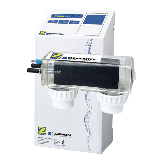
- Page 1 LM2/LM3 Series Troubleshooting Manual...
-
Page 2: Safety Instructions
EQUIPMENT WATER PRESSURE HAZARD • Always turn pump off prior to installing or removing any Clearwater cell. Your pump/filter system is operated under pressure and the pressure must be released before you begin work. Please see your pump/filter owner’s manual for further instructions. -
Page 3: Table Of Contents
Table of Contents Safety Instructions . . . . . . . . . . . . . . . . . . . . . . . . . . . . . 2 Calcium Build-up On Cell . -
Page 4: Circuit Breaker
Circuit Breaker Reset Circuit Breaker 1 . Turn off power supply . 2 . Remove chlorinator from wall . 3 . Find circuit breaker on bottom near power cord . 4 . Push button in . 5 . Replace chlorinator on wall . 6 . -
Page 5: Testing Power Path
Testing Power Path 1 . Turn off power supply . 2 . Remove chlorinator from wall . 3 . Remove 4 screws to remove cover (support cover and leave ribbon wire connected to power PCB) . 4 . Turn on power supply . 5 . -
Page 6: Chlorinator Not Operating
Chlorinator Not Operating Are there any lights visible? Push On / Off Button See pg. 8. or turn on LM3 via controller Is the resettable circuit breaker tripped? Reset circuit breaker. Is there power at timer or switch? (see circuit breaker pg. 4) *If breaker continues to trip Refer customer to a qualified replace PC board (see pg. -
Page 7: No Chlorine Reading
No Chlorine Reading Are there any lights visible? See pg. 6. Will the output lights go all the way up? Chlorinator is working properly. Recommend 1. Is salt level 4000 ppm? to customer to have water sample checked by dealer. Add salt according to chart in Owner’s Manual. -
Page 8: Output Lights Will Not Go To 100
Output Lights Will Not Go to 100% Is salt level 4000 ppm or higher? Add salt according to chart Check there is 220V incoming power. in Owner’s Manual. Have qualified electrician rewire chlorinator to 220V. Is water temperature below 65° F? Add salt to compensate. -
Page 9: Output Lights Will Not Go Down
Amber Output Light Blinking Press and hold service button Chlorinator is in a rest mode before it (located under the “C” in CLEARWATER) reverses polarity. Wait 5-10 minutes to speed up the reversing process. and check again. -
Page 10: No Flow Light Is On
No Flow Light Is On Is the pump moving water? Is the blue sensor wire attached There is a flow related problem and in good condition? with pool equipment. Disconnect sensor clip until pool equipment is repaired. Repair / attach blue sensor wire end to sensor on cell. -
Page 11: Add/Check Salt Light Is On
Add/Check Salt Light Is On Is salt level 4000 ppm or higher? Add salt according to chart in Owner’s Manual. Is water below 65 deg. F? Test touch pad PCB. Note: The LM3 may have the check salt (see touch pad PCB pg. 15) light on at low output. -
Page 12: Chlorine Reading Too High
Chlorine Reading too high Do the output lights go up and down? Check touch pad PCB. Reduce output setting. (see Touch Pad PCB pg. 15) Reduce pump run time. Remove blue sensor wire from cell to stop production for longer than one day at a time. LM3 - Disconnect plug cap. -
Page 13: Reversing Polarity
1 . With power on, be sure chlorinator is NOT in super-chlorinate mode . 2 . Locate service button under the CLEARWATER Logo on LM2 model or above the “3” of LM3 logo . 3 . Press and hold service button down . -
Page 14: Lm3 Interface Instructions
LM3 Interface Instructions Remove the LM3 power pack cover and connect the 4-conductor communication wire to the “eos com” terminal block on the LM3 control PCB, mounted in the LM3 cover . The wiring configurations for various controllers are as shown below: Polaris Eos Jandy Aqualink RS Pentair IntelliTouch... -
Page 15: Touch Pad Pcb
After initialization for both the controller and the LM3, a software connection should have been made . A valid connection can be verified by observing the menu screen of the controller being used . If the chlorinator does not appear to have made a connection, try resetting both the LM3 and the controller . -
Page 16: Pc Board Replacement For The Lm2-15/Lm3-15
PCB Replacement for the LM2-15 / LM3-15 When replacing a Clearwater LM2 or LM3 series PC board, please note that there is a difference between the models 15 and 24/40 . The LM2-15 or LM3-15 can be identified by either the label or the serial number . -
Page 17: Pcb Replacement For Lm2-24/3-24 Or 2-40/3-40
PCB Replacement for LM2-24/3-24 or 2-40/3-40 1 . Disconnect power supply . 2 . Remove chlorinator from wall . 3 . Remove 4 screws to remove cover . 4 . Remove ribbon wire connector from power PCB and set cover aside . 5 . -
Page 18: Triac Screws
Triac Screws The triac screws are the 3 screws at the base of the power PCB . It is imperative that these screws be tightened all the way . The triac tabs are used to transfer heat from the power PCB to the back panel of the chlorinator . If the triac screws are NOT tight, the power PCB will overheat and be damaged. -
Page 19: Lm2 Exploded Diagram & Parts List
LM-2 Series - S - USA LM2 Powerpack Cell Complete Part # Description Part # Description Part # Description W000351 Screw W052031 Transformer cables W200891 LM2-24 complete cell (Packed) W000131 Pop rivet W000551 Washer s/proof W200911 LM2-40 complete cell (Packed) W000281 Washer s/proof W000681... -
Page 20: Lm3 Exploded Diagram & Parts List
LM-3 Series - USA LM3 Powerpack Cell Complete No. Part # Description No. Part # Description W000281 Washer S/Proof W052341 LM3 Output Cable Standard 6’ W000131 Pop Rivet W042342 LM3 Terminal Cover W000351 M3 X 8mm Screw W001091 Black PCB Standoff W042462 LM3 Locking Ring W000261...
Need help?
Do you have a question about the Zodiac LM2 Series and is the answer not in the manual?
Questions and answers