
Related Manuals for Sony SRS-T55


Summary of Contents for Sony SRS-T55
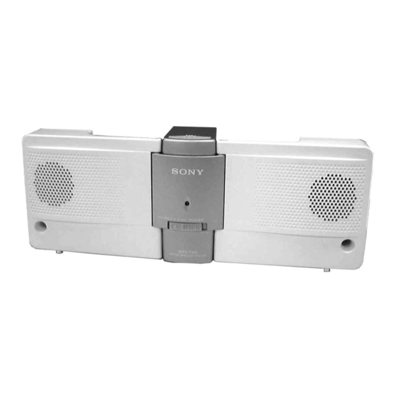
- Page 1 SRS-T55 SERVICE MANUAL E Model Ver 1.0 2001.03 SPECIFICATIONS ACTIVE SPEAKER SYSTEM Sony Corporation 9-873-102-11 2001C0200-1 Audio Entertainment Group © 2001.3 General Engineering Dept.
-
Page 2: Table Of Contents
SRS-T55 TABLE OF CONTENTS Notes on chip component replacement • Never reuse a disconnected chip component. Specifications ................1 • Notice that the minus side of a tantalum capacitor may be dam- aged by heat. 1. GENERAL ..............2 2. DISASSEMBLY 2-1. -
Page 3: Disassembly
SRS-T55 SECTION 2 DISASSEMBLY • The equipment can be removed using the following procedure. Front section Speaker AMP board, DC Jack board Battery box Note : Follow the disassembly procedure in the numerical order given. 2-1. BATTERY BOX 7Remove soider... -
Page 4: Amp Board, Dc Jack Board
SRS-T55 2-3. AMP BOARD, DC JACK BOARD Lid, battery case 1Screws (+ P2X6) Box (L), battery Box (R), battery Cord (with plug) DC Jack board AMP board 6Remove solder (two places) 4Remove solder (five places) -
Page 5: Diagrams
SRS-T55 SECTION 3 DIAGRAMS 3-1. PRINTED WIRING BOARDS SPEAKER(L) 8Ω DC JACK BOARD (SIDE A) AMP BOARD (SIDE A) Semiconductor Location Ref. No. Location DC IN 6V 1-679-480- 1-679-473- (12) (12) SPEAKER(R) (INPUT) 8Ω DC JACK BOARD (SIDE B) AMP BOARD (SIDE B) -
Page 6: Schematic Diagram
SRS-T55 3-2. SCHEMATIC DIAGRAM • IC BLOCK DIAGRAMS IC1,2 TEA2050D-013TR 17 16 15 14 13 12 THERMAL PROTECT START CIRCUIT DECOUPLING Note: • All capacitors are in µF unless otherwise noted. pF: µµF 50 WV or less are not indicated except for electrolytics and tantalums. -
Page 7: Exploded Views
SRS-T55 SECTION 4 EXPLODED VIEWS NOTE : • -XX, -X mean standardized parts, so they • The mechanical parts with no may have some difference from the original reference number in the exploded one. views are not supplied. • Items marked “ * ”are not stocked since they •... -
Page 8: Electrical Parts List
SRS-T55 SECTION 5 DC JACK ELECTRICAL PARTS LIST NOTE : • Due to standardization, replacements in the • SEMICONDUCTORS When indicating parts by reference num- In each case, u : µ , for example : parts list may be different from the parts ber, please include the board. - Page 9 SRS-T55 Ref. No. Part No. Description Remark ACCESSORIES & PACKING MATERIALS ******************************** 3-224-729-21 MANUAL, INSTRUCTION (ENGLISH,FRENCH,GERMAN,SPANISH,DUTCH, ITALIAN,PORTUGUESE,SWEDISH)
- Page 10 SRS-T55 REVISION HISTORY Clicking the version allows you to jump to the revised page. Also, clicking the version at the upper right on the revised page allows you to jump to the next revised page. Ver. Date Description of Revision...
Need help?
Do you have a question about the SRS-T55 and is the answer not in the manual?
Questions and answers