Table of Contents
Advertisement
VERSION 1-10
Instruction Manual
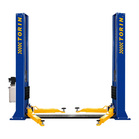
Item:T9000-2BP-22
Model:QJY240C
2 Post Light Duty Automotive Equipment Lift
Symmetric Floor Plate
Maximum Lifting Capacity 9,000 lbs
PLEASE READ ENTIRE MANUAL PRIOR TO INSTALLATION.
This equipment must never be operated without reading this manual and the safety
Safe Operating Temperature is between 40°F – 105°F (4°C - 41°C) Operating
Advertisement
Table of Contents

Related Manuals for Torin QJY240C

Summary of Contents for Torin QJY240C
- Page 1 VERSION 1-10 Instruction Manual Item:T9000-2BP-22 Model:QJY240C 2 Post Light Duty Automotive Equipment Lift Symmetric Floor Plate Maximum Lifting Capacity 9,000 lbs PLEASE READ ENTIRE MANUAL PRIOR TO INSTALLATION. This equipment must never be operated without reading this manual and the safety...
-
Page 2: Table Of Contents
OWNER’S RESPONSIBILITY DO NOT OPERATE OR REPAIR THIS EQUIPMENT WITHOUT READING THIS MANUAL. To maintain the lift and user safety, the responsibility of the owner is to read and follow these instructions: Follow all installation and operation instructions. Make sure installation conforms to all applicable Local, State, and Federal Codes, Rules, and Regulations;... -
Page 3: Warning Paragraph
Warning Paragraph The operation manual should be kept near the equipment at all times. Please be sure to make sure that ALL USERS read this manual before use and operation. Please read carefully the entire contents of this manual prior to installation and operation. By proceeding you agree that you fully understand and comprehend the full contents of this manual. -
Page 4: Warranty
Warranty 2- Post Light Duty Automotive Lift Warranty Coverage 1 Year Structural Warranty (Materials and workmanship must be free of defects.) 1 Year Parts Coverage (All other assembly components and parts, such as; cables, sheaves, hydraulic components, power units, chains, valves, switches, hoses, air cylinders, fittings, misc…) 1 year service coverage on labor with return of parts The warranty does not extend to.: Lifting pads and extensions. - Page 5 Operator Training and Safe Practices Precautions and Safety should always be followed when Installing and Operating this lift. READ AND UNDERSTAND ALL SAFETY INSTRUCTIONS AND DECALS INCLUDED ON AND WITH THE LIFT. READ AND FOLLOW ALL SAFETY WARNING PROCEDURES IN THIS MANUAL BEFORE OPERATING LIFT. ·...
-
Page 6: Operator Training And Safe Practices
Operator Training and Safe Practices IMPORTANT INFORMATION: · USE LIFT CORRECTLY. Use lift in the proper manner. Never use lifting adapters other than what is approved by the manufacturer. After positioning the vehicle on the lift runways, set the emergency brake, make sure the ignition is off, the doors are closed, overhead obstructions are cleared ·... -
Page 7: Safety Instructions
Safety Instructions: 1. Do not raise a vehicle on the lift until the installation is completed as described in this manual. 2. Technicians should be trained to use and care for the lift by familiarizing themselves with the publications listed above. The lift should never be operated by an untrained person. 3. -
Page 8: Safety Requirements
Safety Requirements DO NOT operate or repair this equipment without reading this manual. Failure to comply with these Instructions can result in serious bodily harm and void product warranty. Make sure you have extra help or heavy duty lifting equipment when unloading and assembling the lift. Please read the safety procedures and operating instructions in this manual before installing or operating the equipment. -
Page 10: Lockout Procedure
Lockout Procedure Purpose This procedure establishes the minimum requirements for the lockout of energy that could cause injury personnel by the operation of lifts in need of repair or being serviced. All employees shall comply with this procedure. Responsibility The responsibility for assuring that this procedure is followed is binding upon all employees and service personnel from outside service companies (i.e., authorized installers, contactors, etc.). -
Page 11: Wire Rope Inspection
Wire Rope Inspection (Knowing when to replace your cables!) These pictures will help you assess when you will need to replace wire rope. All wire rope, sheaves and guide rollers in continuous service should be observed during normal operation and visually as per the scheduled maintenance. A complete and thorough inspection of all ropes in use must be made as below and all rope which has been idle for a period of a month or more should be given a thorough inspection before it is put back into service. Factors such as abrasion, wear, fatigue, corrosion, improper winding and kinking are often of greater significance in determining if a wire rope is usable. Use the pictures as shown as guide for determining when to replace your wire rope. Recommended Lubrication Product: Silver Streak Wire Rope Lubricant (#199) is a heavy duty extreme pressure lubricant specially formulated to provide extended service life over a wide range of temperatures to all types of wire ropes. Check all guide rollers, sheaves and hardware that ... -
Page 12: Concrete Foundation Specifications And Requirements
Concrete Foundation Specifications and Requirements Less than 10,000 lbs 2-Post Models 4 Inch Min. Thickness / 3,000 PSI (4000 PSI Recommended) FOUNDATION and ANCHORING REQUIREMENTS Before installing your new lift, check the following. Selecting Lift Location: Always use architects building plans when available. Check layout dimension against floor plan requirements making sure that adequate space is available. -
Page 13: Post Tension Concrete
POST TENSION CONCRETE DO NOT CUT OR DRILL THROUGH A POST TENSION CABLE. Do not disturb, bolt up, or apply load to adhesive anchors prior to the full cure of the adhesive. Metal anchors and fasteners will corrode and may lose load-carrying capacity when installed in corrosive environments or exposed to corrosive materials. - Page 14 Expansion Anchor ¾” x 5-1/2” Anchor size is same as drill bit size ( .775" to .787“ ) Use a hammer drill with a Carbide tip, 3/4" diameter, solid drill bit. The bit tip diameter should be to ANSI Standard B95.12-1977.
-
Page 15: Troubleshooting
Troubleshooting The power unit does not run: - Check electrical supply breaker or fuse. - Check to see if limit switch is being contacted by a tall vehicle. - Check micro-switch and connections in motor control box. - Check voltage to the motor. - Check micro-switch and connections on the overhead switch. -
Page 16: Monthly Maintenance
Troubleshooting The lift will only lower completely to 1” from the floor. -Check that the safety latches are disengaged. - Adjust cable as needed to assure that cables have not been over tightened and check that both safety latches are disengage. -
Page 17: Pre-Installation Procedure
Pre-Installation Procedu res Before beginning your installation make sure you read the installation manual and insure all instructions and safety guidelines are fully understood. Check that all component parts are accounted for. Locate the installation area, identify the center line of the bay and mark the floor. Also mark the center of bay entrance door. Connect these two points with a short chalk line in the area where lift will be located. -
Page 18: Installation Tools Required
Installation Tools Required: 16ft. Measuring Tape Chalk Line and Chalk Heavy Duty Metal Wire Cutters 3 ft Crow Bar Full set of Metric Wrenches and Ratchet Set Full set SAE Wrenches and Ratchet Set Metric and SAE Allen Key Sets Hammer Rubber Mallet Screwdrivers... -
Page 19: Installation Procedure
INSTALLATION PROCEDURE STEP 1: After unloading the lift, place it near the intended installation location. STEP 2: Remove the shipping bands and packing materials from the lift. The power unit will be unpacked from the top. Note: Be care-ful not to drop power unit on heavy end STEP 3: Open the wrapping, remove the parts and parts boxes from the packaging. - Page 20 Lifting Chain Step 6: Verify that chain is connected and secure. The Manufacturer has pre-adjusted the chain and should not be removed. (Fig 8) STEP 7: Install top mounting plates on each column. Safety Latches Step 8: Pull safety latch cable on front of lifting carriage.
- Page 21 Columns STE P 9: Raise the columns and position the columns facing each other. The outside base plates measurements are as shown for each unit (Fig. 1, 2) for correct measu rement to your lift). Square using a chalk line and measuring from rear points on base plates (mark your positioning within 1/16”).
- Page 22 Equalizing Cables STEP 14: After the columns have been securely fastened. Raise the both lifting carriages to second safety lock position. (Double check to make sure carriage is secure before routing cable.) STEP 15: (see Fig. #2) After raising the columns route the cables in each column cables as illustrated (Fig #?). the cable from the front tie off point of the carriage, the stop connector will seat on the front stop Route mount.
- Page 23 Fig 12 Fig 12...
- Page 24 Power Unit and Hydraulic System STEP 18: Mount the power unit on the side powerside column bracket using the four M10 x 20mm bolts and nuts. (Fig 14) A. Install the #6 SAE o-ring fitting on the power port. (Fig 13) B.
- Page 25 STEP 20: Connect the Electrical hookup to the power unit; 220V Single Phase. It is recommended that a 220 Volt, 30 Amp twist lock plug be installed in the power line just ahead of the power unit. Use wire capable of supporting a 30-amp circuit. Warning: –...
- Page 26 Base Plate Step 21: Install base plate with 4 - M8 x 15mm Countersink Screws. (Fig 17) Fig 17 Arms STEP 22: The “half moon” gear restraints on each lifting Fig 18 arm are already installed. Loosen Allen Screws Gear restraints will need to be adjusted once installed on lifting carriages.
- Page 27 Step 14: Install lifting carriage arm drop pins. (Fig. 20) Fig 20 Equalizing Cables Important Notice: Equalizing Cables must be checked weekly. The tension should not be any more than 1/2" of tension slack. Failure to do this could cause an uneven lift and could cause DANGER. Equalizing cables should always be adjusted so that safety latches are in sync set on safety locks Synchronizing Safety Latches STEP 23: Without any vehicle on the lift. Cycle the lift up and down several times to insure safety latches engage properly and all air is removed from the hydraulic system.
-
Page 28: Post Installation Procedure
Microswitch Step 25: If this unit includes a safety micro switch test. Verify that micro switch is operating correctly. Operate lift and apply pressure to micro switch with a piece of non-conductive material to push down on switch. A chance of shock could occur if wiring has not been installed incorrectly. This will insure motor shuts off prior to any part of vehicle coming in contact with overhead crossbeam or preset height restrictions micro switch location. - Page 29 NOTES: ______________________________________________________________________________ ______________________________________________________________________________ ______________________________________________________________________________ ______________________________________________________________________________ ______________________________________________________________________________ ______________________________________________________________________________ ______________________________________________________________________________ ______________________________________________________________________________ ______________________________________________________________________________ ______________________________________________________________________________ ______________________________________________________________________________ ______________________________________________________________________________ ______________________________________________________________________________ ______________________________________________________________________________ ______________________________________________________________________________...
- Page 30 NOTES: ______________________________________________________________________________ ______________________________________________________________________________ ______________________________________________________________________________ ______________________________________________________________________________ ______________________________________________________________________________ ______________________________________________________________________________ ______________________________________________________________________________ ______________________________________________________________________________ ______________________________________________________________________________ ______________________________________________________________________________ ______________________________________________________________________________ ______________________________________________________________________________ ______________________________________________________________________________ ______________________________________________________________________________ ______________________________________________________________________________...
- Page 31 NOTES: ______________________________________________________________________________ ______________________________________________________________________________ ______________________________________________________________________________ ______________________________________________________________________________ ______________________________________________________________________________ ______________________________________________________________________________ ______________________________________________________________________________ ______________________________________________________________________________ ______________________________________________________________________________ ______________________________________________________________________________ ______________________________________________________________________________ ______________________________________________________________________________ ______________________________________________________________________________ ______________________________________________________________________________ ______________________________________________________________________________...
- Page 32 Parts Diagram...
- Page 33 Parts List...
- Page 34 COMPANY INFO BACK PAGE...
Need help?
Do you have a question about the QJY240C and is the answer not in the manual?
Questions and answers