Advertisement
Quick Links
Alexander Schleicher GmbH & Co. Segelflugzeugbau
Model:
Serial Number:
Registration letters:
TC Data Sheet No.:
Issue:
Pages identified by "App." are approved by the au-
thority as shown below:
................................................
Signature
................................................
Aviation Authority
................................................
Stamp
................................................
Original Date of Approval
This powered sailplane is to operate only in compliance with the operat-
ing instructions and limitations contained herein.
The translation has been done by best knowledge and judgment. In any case
D-36163 Poppenhausen - Germany
Flight Manual
for the powered sailplane
ASH 31 Mi
the original text in German is authoritative.
ASH 31 Mi
EASA.A.538
October 01, 2011
Advertisement

Related Manuals for Alexander Schleicher ASH 31 Mi

Summary of Contents for Alexander Schleicher ASH 31 Mi
- Page 1 Alexander Schleicher GmbH & Co. Segelflugzeugbau D-36163 Poppenhausen - Germany Flight Manual for the powered sailplane ASH 31 Mi Model: ASH 31 Mi Serial Number: Registration letters: TC Data Sheet No.: EASA.A.538 Issue: October 01, 2011 Pages identified by “App.” are approved by the au- thority as shown below: ..........
- Page 3 ASH 31 Mi Flight Manual Flight Manual Section 0 0.1 Record of Revisions Any revision of the present manual, except weighing data established from time to time, must be recorded in the following table "Record Of Revisions" (pages 0.2/0.3) and in case of approved Sections endorsed by the Authority in charge.
- Page 5 ASH 31 Mi Flight Manual Flight Manual Record of Revisions Rev. Date of Date of Date of Ref. / Section & Pages Affected Approval No.. Issue Approval Insertion Signature 0.2 0.4 0.5 0.6 2.6 2.7 EASA 3.11 3.12 Minor TN 4 4.12 4.14 bis 4.17...
- Page 7 ASH 31 Mi Flight Manual Flight Manual Record of Revisions Rev. Date of Date of Date of Ref. / Section & Pages Affected Approval No.. Issue Approval Insertion Signature Issue: 01.10.2011 mh Revision:...
- Page 9 ASH 31 Mi Flight Manual Flight Manual 0.2 Index of Effective Pages Section Page Date Section Page Date Titel page --- 01.10.2011 3.6 01.10.2011 App. 3.7 01.10.2011 App. 0.1 01.10.2011 3.8 01.10.2011 App. 0.2 01.04.2015 3.9 01.10.2011 App. 0.3 01.10.2011 3.10 01.10.2011...
- Page 11 ASH 31 Mi Flight Manual Flight Manual 4.27 01.10.2011 7.5 01.10.2011 App. 4.28 01.10.2011 7.6 01.10.2011 App. 4.29 01.10.2011 7.7 01.10.2011 App. 4.30 01.10.2011 7.8 01.10.2011 App. 4.31 01.10.2011 7.9 01.10.2011 App. 4.32 01.10.2011 7.10 01.10.2011 App. 4.33 01.10.2011 7.11 01.10.2011 App.
- Page 13 ASH 31 Mi Flight Manual Flight Manual 7.40 01.10.2011 8.4 01.10.2011 7.41 01.10.2011 8.5 01.10.2011 7.42 01.10.2011 8.6 01.10.2011 7.43 01.10.2011 8.7 01.10.2011 7.44 01.10.2011 8.8 01.10.2011 8.9 01.10.2011 8.1 01.10.2011 8.2 01.10.2011 9.1 01.10.2011 8.3 01.10.2011 9.2 01.10.2011 Issue: 01.10.2011 mh...
-
Page 15: Table Of Contents
ASH 31 Mi Flight Manual Flight Manual 0.3 Table of Contents Section Record of Revision, List of Effective Pages, Table of Contents General Section without approval) Operating Limitations and Data (Approved Section) Emergency Procedures (Approved Section) Normal Operating Procedures Approved Section) -
Page 17: General
ASH 31 Mi Flight Manual Flight Manual Section 1 General Introduction Type Certification Basis Special Annotations Description and Technical Data Three View Drawing Issue: 01.10.2011 mh Revision:... - Page 18 1.2 Type Certification Basis This powered sailplane of the type designation ASH 31 Mi is type ap- proved by the European Aviation Safety Agency (EASA) in compliance with Certification Specifications for Sailplanes and Powered Sailplanes, issued 24.
- Page 19 ASH 31 Mi Flight Manual Flight Manual 1.3 Special Annotations Passages in this manual, which are of special importance for flight safe- ty or handling, have been emphasized by being prefixed by one of the following annotations: "WARNING" means that the non-observation of the...
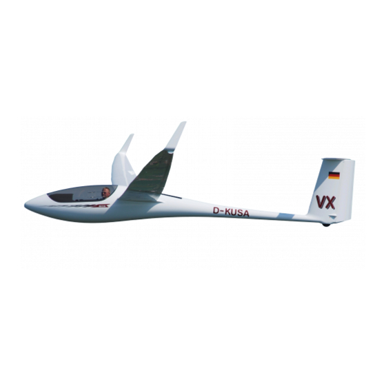
- Page 20 - and their meteorological conditions, which would be out of reach of a pure sailplane. The ASH 31 Mi is a shoulder wing sailplane with damped T-tail and sprung, retractable landing gear with hydraulic disc brake. The wing is...
- Page 21 ASH 31 Mi Flight Manual Flight Manual Technical Data: Span version 18 m (59.06 ft) 21 m (68.90 ft) Span 18,0 m (59.06 ft) 21,0 m (68.90 ft) Fuselage length 7,10 m (23.30 ft) Height (Fin and Tail Wheel) 1,50 m (4.92 ft) Max.
- Page 22 ASH 31 Mi Flight Manual Flight Manual Three View Drawing Fig. 1.5-1 Issue: 01.10.2011 mh Revision:...
-
Page 23: Operating Limitations And Data
ASH 31 Mi Flight Manual Flight Manual Section 2 Operating Limitations and Data Introduction Air Speed ASI Markings Power Plant Power Plant Control Unit Markings Masses (Weights) Centre of Gravity Approved Manoeuvres Manoeuvring Load Factors 2.10 Flight Crew 2.11 Types of Operation 2.12 Fuel... - Page 24 This Section contains operating limitations, instrument markings and cockpit placards required for the safe operation of the powered sail- plane ASH 31 Mi and its systems, installations, and equipment provided as factory-standard.. The operating limitations included in this Section and in Section 9 are EASA-approved.
- Page 25 ASH 31 Mi Flight Manual Flight Manual SPEED REMARKS This speed must not be 200 km/h Maximum permissible exceeded in strong 108 kts speed for rough air turbulence. Examples of rough air are lee- 124 mph wave rotors, thunder- clouds, etc...
- Page 26 ASH 31 Mi Flight Manual Flight Manual Maximum aero towing Do not exceed this 160 km/h speed during aero tow- speed 86 kts ing. 99 mph Maximum speed with Do not exceed this 180 km/h speed with power plant propeller extended 97 kts idling.
- Page 27 ASH 31 Mi Flight Manual Flight Manual 2.3 Airspeed Indicator Markings Airspeed indicator markings and their colour-code significance are shown below. Marking IAS value or range Significance 90 – 160 km/h Positive Flap Operating White Arc 49 – 86 kts Range 56 –...
- Page 28 ASH 31 Mi Flight Manual Flight Manual 2.4 Power-Plant Engine: IAE50R-AA Maximum power, take-off: 37.3 kW (3 minute limit) 7750 rpm continuous: 35.8 kW 7100 rpm Maximum take-off revs: 7750 rpm Maximum continuous revs: 7100 rpm Maximum overspeed revs: (20 sec.)
- Page 29 ASH 31 Mi Flight Manual Flight Manual 2.5 Power-Plant Control Unit Markings The following table shows the markings of the digital ILEC Engine Con- trol Unit and explains the meaning of the LED colours in relation to the rpm indication:...
- Page 30 Datum" which is identical with the wing leading edge at the wing root rib. One example of calculating C.G. positions is given in Section 6 of the ASH 31 Mi Maintenance Manual. 2.8 Approved Manoeuvres This powered sailplane is approved for normal sailplane and powered sailplane operation (Airworthiness Category "Utility").
- Page 31 ASH 31 Mi Flight Manual Flight Manual 2.9 Manoeuvring Load Factors Maximum manoeuvring load factors:: maximum positive load factor + 5.3 maximum negative load factor - 2.65 at an air speed of 200 km/h ( 108 kts, 124 mph) At increasing air speeds, these values will be reduced to:...
- Page 32 ASH 31 Mi Flight Manual Flight Manual 2.12 Fuel Only fuel WITHOUT two-stroke oil must be refilled. Capacity of the fuel tanks Litrs. US Gal. fuselage tank: 16.0 4.23 each wing tank (if fitted): 15.0 3.96 Standard fuel capacity fuselage tank only: 16.0...
- Page 33 ASH 31 Mi Flight Manual Flight Manual 2.13 Minimum Equipment Minimum Equipment consists of: 1 ASI indicating up to 300 km/h = 162 kts 1 Altimeter 1 4-part seat harness (symmetrically) 1 Magnetic Compass 1 ILEC engine control unit 1 rear view mirror...
- Page 34 ASH 31 Mi Flight Manual Flight Manual 2.15 Operating Limitations Placard This placard is fixed at the left cockpit sidewall and contains the most important Mass and Speed Limitations App. Issue: 01.10.2011 mh Revision: 2.12...
- Page 35 ASH 31 Mi Flight Manual Flight Manual Reduced minimum cockpit load by fitting removable trim ballast in front of the pedal assembly: see Section 7.13 The baggage compartment load must not exceed 15 kg = 33 lb Issue: 01.10.2011 mh App.
- Page 37 ASH 31 Mi Flight Manual Flight Manual Section 3 Emergency Procedures Introduction Canopy Jettisoning Bailing Out Stall Recovery Spin Recovery Spiral Dive Recovery Engine Failure Fire Other Emergencies in Powered Flight 3.10 Other Emergencies Issue: 01.10.2011 mh App. Revision:...
-
Page 38: Emergency Procedures (Approved Section)
ASH 31 Mi Flight Manual Flight Manual 3.1 Introduction This Section contains Check Lists, summarising procedures recom- mended in the case of emergencies, in the form of brief headings. This is followed by a more detailed description. Emergency Procedures Canopy Jettisoning... - Page 39 ASH 31 Mi Flight Manual Flight Manual Spinning (When power plant running: set throttle to IDLE) Apply opposite rudder and at the same time, relax back pressure on stick until rotation stops, centralise rudder and immediately pull out gently from dive.
- Page 40 ASH 31 Mi Flight Manual Flight Manual 3.2 Canopy Jettisoning If, during propeller-extended flight, jettisoning the canopy is unavoid- able, the (running) propeller must at first be moved into a position which is not dangerous for the pilot. Switch off the ignition and engage the propeller stop.
- Page 41 3.4 Stall Recovery In normal or circling flight, easing the control column forward will always lead to recovery. Due to its aerodynamic qualities the ASH 31 Mi will immediately regain flying speed. 3.5 Spin Recovery Intentional spinning is not permitted. The procedure hereafter describes how to terminate unintended spinning.
- Page 42 ASH 31 Mi Flight Manual Flight Manual CAUTION: Furthermore, spin recovery will be achieved more quickly if flap deflection is reduced. It is advisable to reduce circling flap setting to neutral flap setting (Flap 4). Spinning is not noticeably affected by extending the...
- Page 43 (Fuselage tank contents?) If the above points are correct, the fault cannot be rectified in flight, the propeller should be retracted and the ASH 31 Mi should from then on be operated as a pure sailplane. Retract propeller in the normal manner in accordance with the check list.
- Page 44 ASH 31 Mi Flight Manual Flight Manual propeller stop should be engaged at a speed of about 90 km/h (49 kts) - even with the propeller still running. This will help to stop the propeller more quickly. Then the propeller must be retracted approx. "halfway in", which is the minimum position.
- Page 45 ASH 31 Mi Flight Manual Flight Manual 3.8 Fire (1) Fire with propeller extended A fire in the engine compartment is indicated by a red blinking diode on the instrument panel. Further details are given in Section 7.9. Monitor as per Check List (4) and land as quickly as possible, if possi- ble avoid severe manoeuvre or gusts.
- Page 46 ASH 31 Mi Flight Manual Flight Manual 3.9 Other Emergencies in Powered Flight (1) Strong Noise Development Due To Defective Exhaust Silencer If the noise from the exhaust silencer is considerably increasing, a fail- ure of the exhaust system must be taken into account. As hot exhaust fumes may cause fire, the engine must be stopped immediately or after having reached a safety altitude respectively.
- Page 47 ASH 31 Mi Flight Manual Flight Manual the propeller rotates sufficiently for an engine start. Keep in mind to activate the ignition! Insufficient fuel pressure In case the Red LED blinks on the ILEC Engine Control Unit and the display indicates "FUELPRES", first check the position of the fuel cock.
- Page 48 3.10 Other Emergencies (1) Jammed Elevator Control System If the flap control is jammed, the ASH 31 Mi is converted into an aircraft with fixed wing profile. However, in case of an emergency with the ele- vator control jammed, the pilot will not always think of the fact that the flaps at least will allow him some degree of pitch control in order to improve his position for bailing out or to avoid it at all.
- Page 49 If the landing gear cannot be lowered, the ASH 31 Mi should be touched down with landing flaps (Flap L) selected, air brakes retracted as far as possible, in a flat angle and without stalling on to the ground.
- Page 50 ASH 31 Mi Flight Manual Flight Manual because a landing at a higher wing loading would be preferable to a landing with a considerably asymmetric ballast loading. If a failure of the valves should cause asymmetric loading, the flight should be terminated with utmost care, where by an adequate margin above the minimum speed have to be observe as wing dropping and spinning with asymmetric ballast load are not permitted.
-
Page 51: Normal Operating Procedures
ASH 31 Mi Flight Manual Flight Manual Section 4 Normal Operating Procedures Introduction Rigging and Derigging Daily Inspection Pre-Flight Checks Normal Operation and Recommended Speeds 4.5.1 Operating the Power-Plant 4.5.2 Winch Launch and Auto Tow Launch 4.5.3 Aero tow 4.5.4 Free Flight 4.5.5... - Page 52 ASH 31 Mi Flight Manual Flight Manual 4.1 Introduction This Section contains Check Lists for the daily inspection and pre-flight checks. It also describes normal operating procedures. Normal opera- tion procedures associated with the sailplane, if equipped with various ancillary systems and equipment not included as standard equipment, are described in Section 9.
- Page 53 ASH 31 Mi Flight Manual Flight Manual it is recommended that the landing gear should be extended at this stage, and rigging completed with the aircraft standing on its wheel. If flexible fuel tanks are fitted in the wings, their fuel hoses should now (or, at the latest, after filling up) be connected to that from the fuselage tank.
- Page 54 ASH 31 Mi Flight Manual Flight Manual CAUTION: Of course always install outer wing panels with the same wingspan. Insert winglets into the wingtip groove until the safety pin engages and tape around the joint. CAUTION: Always check the proper locking of the winglet’s safety catch.
- Page 55 ASH 31 Mi Flight Manual Flight Manual 12. Now use the Check List (see the following para. 4.4) to carry out a pre-flight check. Under point 3. "Control surface clearances at trail- ing edge min. 1.5 mm = 1/16 in!" check that the wing control sur- faces have that minimum clearance from each other and from the inboard and outboard wing cut-out edges.
- Page 56 ASH 31 Mi Flight Manual Flight Manual 4.3 Daily Inspection Before flying operations, the aircraft must be thoroughly inspected and its controls checked; this also applies to aircraft kept in the hangar, as experience shows them to be vulnerable to hangar-packing damage and small animals.
- Page 57 ASH 31 Mi Flight Manual Flight Manual l) Check that rudder, tailplane and elevator are correctly assembled, and for damage or excessive play. Is the bolt for the tailplane firmly tightened and locked? Are trim weights installed in the fin? For increased cockpit loads refer to loading chart in chapter 6.2.
- Page 58 ASH 31 Mi Flight Manual Flight Manual Daily Inspection of Extended Propeller a) When extending the propeller pay attention to unusual noise and stiffness of operation. b) The most important bolted connections can be checked from above through the open engine bay doors. With one exception they are se- cured with standard stop nuts and therefore, are easy to check.
- Page 59 ASH 31 Mi Flight Manual Flight Manual k) Check the attachment of the moveable intake tube. Is the air filter at the upper end correctly affixed. l) Check limit switch for electric jack for damage and secure seating - including its electric connections.
- Page 60 ASH 31 Mi Flight Manual Flight Manual Tank System (fuel and oil) a) Check that hose connections to the wing tanks are secure and tight. b) Check visually fuselage tank through wheel cut out for damage due to impact from stones and for leaks.
- Page 61 ASH 31 Mi Flight Manual Flight Manual 4.4 Pre-Flight Checks The following Check List containing the most important points is affixed within easy view of the pilot. Issue: 01.10.2011 mh App. Revision: 4.11...
- Page 62 ASH 31 Mi Flight Manual Flight Manual 4.5 Normal Operation and Recommended Speeds 4.5.1 Power-Plant Control and Self-Launch Checklist, extending propeller and starting engine Fuel valve: OPEN Power-plant main switch: ON (ILEC in operation) Switch "Extend Propeller" engaged upwards Green LED "Propeller extended" on ?
- Page 63 ASH 31 Mi Flight Manual Flight Manual Cold start (very cold, strongly cooled engine) Propeller CLEAR ? Set THROTTLE to "IDLE" (at lowest position). Push STARTER button max. 5 seconds If the engine fails to start, push STARTER button again, after a short recovery for starter battery.
- Page 64 Maximum -take-off revs: at 7750 rpm for maximum 3 minutes Maximum -take-off revs: at 7100 rpm The power plant of the ASH 31 Mi gives the possibility to self-launch with good climbing performance, extending the operational range of a pure sailplane. It is advisable to familiarize oneself with the extending and starting procedures initially within safe reach of an airfield, before attempting a cross-country flight.
- Page 65 ASH 31 Mi Flight Manual Flight Manual lations as normal aviation engines, and therefore cannot be expected to be quite as reliable. A minimum safe height for extending the propeller and starting the en- gine must be met. The criterion is that it must be possible to retract the propeller again and carry out a normal sailplane out landing if the en- gine cannot be started.
- Page 66 ASH 31 Mi Flight Manual Flight Manual to work properly, causing the engine to develop less than full power. The reason can be a faulty fuel pump or pressure regulator or even a leaking fuel line. WARNING: In this case the engine must be stopped at once and no self-launching must be attempted.
- Page 67 ASH 31 Mi Flight Manual Flight Manual an un-problematic start of the engine. In case of problems, last but not least, an operating error may be assumed. A closed fuel cock is most often the cause of the engine not starting.
- Page 68 ASH 31 Mi Flight Manual Flight Manual (3) Self-Launch - ECU LED OFF ? - Fuel pump 2 as a precaution - After approaching a safe altitude: fuel pump 2 - Reduce, after 3 minutes, the maximum take off power to 7100 rpm For a safe self-launch maximum engine, revolutions should come up to 7000 rpm on the ground.
- Page 69 ASH 31 Mi Flight Manual Flight Manual Nevertheless, in case of cross wind the procedure differs and the tail wheel is loaded by slightly pulling the stick in order to increase direc- tional stability during the ground run. Soft surface runways: Accelerate with wide open throttle at Flap setting 1 and after having gained aileron control, change the flap setting to position 6.
- Page 70 ASH 31 Mi Flight Manual Flight Manual CAUTION: If wing fuel tank(s) is(are) fitted, check that the oil sup- ply is sufficient for the completely intended fuel con- tents. Monitor oil warning light! A detailed description of the ILEC engine control unit is given under Section 7.9.
- Page 71 ASH 31 Mi Flight Manual Flight Manual (7) Retracting the Propeller The propeller stop block must be swivelled into the arc of the propeller only after the engine rpm have almost completely died down and the propeller is only windmilling. Max. speed is 120 km/h (65 kts, 75 mph).
- Page 72 Trim should be set neutral to nose-heavy at any C.G. position. At this trim setting the ASH 31 Mi will assume a gentle climb attitude. With high-powered winches which tend to jerky accelerations, the trim should always be set nose-heavy.
- Page 73 ASH 31 Mi Flight Manual Flight Manual CAUTION: Before Take-Off, check seating position and that con- trols are within reach. The seating position, especially when using cushions, must preclude the possibility of sliding backwards during initial acceleration or steep climb.
- Page 74 ASH 31 Mi Flight Manual Flight Manual NOTE: Inform tug pilot of minimum towing speed. Wing Loading Recommended Towing Speed 40 kg/m = 8.2 lb/ft² 115 km/h = 62 kts = 72 mph 45 kg/m = 9.2 lb/ft² 125 km/h = 68 kts = 78 mph 53 kg/m = 10.9 lb/ft²...
- Page 75 10 % at about 30° bank, and by 20 % at about 45° bank. Low Speed Flight and Stalling Behaviour: The ASH 31 Mi behaves normally in slow and stalled flight. With all C.G. positions flow separation at the fuselage and horizontal tail buffet- ing will give warning of an impending stall.
- Page 76 ASH 31 Mi Flight Manual Flight Manual More specifically, the following would apply: Rudder & Aileron Rudder & Aileron C.G. Position Flap Co-ordinated Crossed rearmost steady spin steady spin spin, leading to spiral spin, leading to central dive slipping turn...
- Page 77 ASH 31 Mi Flight Manual Flight Manual At air speeds above 100 km/h (54 kts, 62 mph) the control forces re- quired to engage Flap setting L will noticeably increase. It is, therefore inadvisable to engage landing Flap L at more than 100 km/h. These high control forces are generated by the very positive camber of the Flaps.
- Page 78 ASH 31 Mi Flight Manual Flight Manual - If you are not familiar with the use of the Flaps as a landing aid, you should initially only use Flap 4 for a landing into a headwind. CAUTION: The danger of a sudden drop makes it inadvisable to reduce Flap setting near the ground.
- Page 79 4.5.7 Flying with Water Ballast For normal European weather conditions, the wing loading of the ASH 31 Mi is already at its best even without additional water ballast. If achieved lift is markedly greater than 2 m/s (400 ft/min), wing loading can be increased up to about 53 kg/m²...
- Page 80 ASH 31 Mi Flight Manual Flight Manual and right valves must remain open during filling. This is an important requirement of the certification standard to prevent inadvertent draining of only one tank. Now the other wing tip is put down while its tank is filled. The valves should be closed and the stopper with marking tape removed from the wing whose tank was filled first.
- Page 81 ASH 31 Mi Flight Manual Flight Manual Water ballast limits: See section 6.3 to determine the maximum allowed amount of water ballast. Draining of Water Ballast: To drain water ballast move the lever at the right cockpit wall is pulled for-wards.
- Page 82 ASH 31 Mi Flight Manual Flight Manual 4.5.8 High Altitude Flight Flutter tests were carried out at about 2000 m msl (6562 ft). As the ASI under-reads at increasing altitude, but since flutter limits for light aircraft are determined by the true air speed, the following limitations apply to...
- Page 83 ASH 31 Mi Flight Manual Flight Manual The pilot must wait until the warm power-plant compo- nents have warmed up the radiator. WARNING: Flights in icing conditions are not advised, especially if the aircraft is wet before climbing through icing level.
- Page 84 Flight Manual Flight Manual 4.5.10 Operation with Power-Plant removed The ASH 31 Mi may be operated as a normal sailplane when the power-plant is removed. However, the procedures for the removal and the reinstallation of the powerplant as per section 2.3.4 of the mainte- nance manual are to be observed to.
-
Page 85: Performance
ASH 31 Mi Flight Manual Flight Manual Section 5 Performance Introduction EASA- Approved Data 5.2.1 ASI Indication Errors 5.2.2 Stall Speeds 5.2.3 Take-Off Performances 5.2.3.1 Take-off Charts 5.2.4 Flight Performance with Engine Running Additional Information 5.3.1 Demonstrated Cross Wind Components 5.3.2 Noise Data... - Page 86 CAUTION: The following diagram only shows the position error of the ASH 31 Mi pressure system, however, does not in- clude the ASI instrument error. Issue: 01.10.2011 mh...
- Page 87 ASH 31 Mi Flight Manual Flight Manual VIAS = Indicated Air-Speed VCAS = Calibrated Air-Speed Issue: 01.10.2011 mh App. Revision:...
- Page 88 ASH 31 Mi Flight Manual Flight Manual 5.2.2 Stall Speeds Stall Speeds in km/h (kts, mph) Indicated Air Speed. Flight Mass Flap- 510 kg* 550 kg 630 kg 700 kg Setting 1124 lb* 1213 lb 1389 lb 1543 lb km/h...
- Page 89 ASH 31 Mi Flight Manual Flight Manual Lowering the landing gear does not affect the stalling speed. With maximum cockpit load and Flap 1 selected the height loss can be up to 60 m (197 ft) until stall is terminated.
- Page 90 ASH 31 Mi Flight Manual Flight Manual Stalling Speed Diagram Issue: 01.10.2011 mh Revision:...
- Page 91 ASH 31 Mi Flight Manual Flight Manual 5.2.3 Take-Off Performance The take-off performances given below are applicable to take-offs on hard and level grass runways and for the aircraft, propeller, and engine in good condition and for the following conditions: Wing span version 18 m (59.1 ft)
- Page 92 For pilots inexperienced in self-launch the following observation may be helpful for estimating a safe self-launch: The flight testing of the ASH 31 Mi demonstrated that take-off and climb characteristics during self-launch are slightly better than for an aerotow behind a powerful 132 kW tug aircraft (e.g.: Robin DR 400). If therefore a safe aerotow may be expected, there will neither be any problems for the self-launch.
- Page 93 ASH 31 Mi Flight Manual Flight Manual Take-off roll Take-off distance to clear a 15 m (50 ft) obstacle Table for 18m (59.1 ft) Wing Span and Take/off Mass 630 kg (1389 lbs) Pressure Temperature Take-off roll distance Take-off dist. to 50 ft height...
- Page 94 ASH 31 Mi Flight Manual Flight Manual Take-off roll Take-off distance to clear a 15 m (50 ft) obstacle Table for 21 m (68.9 ft) Wing Span and Take-off Mass 700 kg (1543 lbs) Pressure Temperature Take-off roll distance Take-off dist. to 50 ft height...
- Page 95 Flight Manual 5.2.4 Flight Performance with Engine Running Climb Rate At msl and normal atmosphere the ASH 31 Mi offers dependent on take-off mass and wing span the data given in following chart at the best climb speed of v...
- Page 96 ASH 31 Mi Flight Manual Flight Manual These consumption figures are based on practical experience and can be exceeded by up to 5 l/h according to the engine manual. Wing span version 18 m (59.1 ft) 21 m (68.9 ft)
- Page 97 ASH 31 Mi Flight Manual Flight Manual 5.3 Additional Information 5.3.1 Demonstrated Cross Wind Components Self Launch 25 km/h (15.5 kts) Winch Launch & Autotow 20 km/h (13.5 kts) Aerotow 20 km/h (13.5 kts) Landing 25 km/h (15.5 kts) 5.3.2 Noise Data...
- Page 98 ASH 31 Mi Flight Manual Flight Manual 5.3.3 Speed Polars Issue: 01.10.2011 mh Verdecken Revision: 5.14...
- Page 99 ASH 31 Mi Flight Manual Flight Manual 5.3.4 Optimum-Performance Flap Settings Issue: 01.10.2011 mh Verdecken Revision: 5.15...
- Page 100 ASH 31 Mi Flight Manual Flight Manual Issue: 01.10.2011 mh Verdecken Revision: Verdecken 5.16...
- Page 101 ASH 31 Mi Flight Manual Flight Manual Section 6 Mass (Weight) and Balance, C.G. Position Introduction Mass (Weight) and Balance Form Acceptable Water Ballast and Fuel Load Recommended C.G. Range Issue: 01.10.2011 mh Revision:...
- Page 102 6.1 Introduction This Section describes the limits of load distribution, inside which the ASH 31 Mi can be safely operated. The data given here apply only to the individual aircraft the serial number of which is specified on the title page of this manual..
- Page 103 ASH 31 Mi Flight Manual Flight Manual 6.2 Mass (Weight) and Balance Form The Mass and Balance Form gives the maximum and minimum load in the pilot's seat, and any additional load still permissible for the baggage compartment and the fuselage fuel tank.
- Page 104 ASH 31 Mi Flight Manual Flight Manual In case the ASH 31 Mi was supplied with 21 and 18 m (68.9 and 59.1 ft) wing panels or upgraded subsequently, the following placard is to be fitted to the cockpit: The minimum cockpit load in 18 m (59.1 ft) configuration is significantly lower compared to the 21 m (68.9 ft) version.
- Page 105 ASH 31 Mi Flight Manual Flight Manual Mass and Balance Form Pilot mass incl. Empty Empty mass Useful load in parachute mass C.G. aft of Inspector’s 1,3) Date of fuselage (18 und 21m) stamp and Weighing (18 und 21m) (59.1and 68.9 ft)
- Page 106 ASH 31 Mi Flight Manual Flight Manual 6.3 Acceptable Water Ballast and Fuel Load The amount of fuel and water ballast is restricted by the following limits: 1. Maximum Take-Off-Weight Maximum take-off weight may not be exceeded. Span 21 m 18 m (68.9 ft)
- Page 107 ASH 31 Mi Flight Manual Flight Manual A) Maximum Permissible Loading with water ballast for all sort of take- off: d sailplane with 21 m (68.9 ft) wing span Pilot mass + Parachute + fuel ( in fuselage tank )
- Page 108 ASH 31 Mi Flight Manual Flight Manual Powered sailplane with 18 m (59.1 ft) wing span Pilot mass + Parachute + fuel ( in fuselage tank ) Empty Mass + Baggage [lb] [kg] [lb] 130 ltrs 120 ltrs 110 ltrs 100 ltrs...
- Page 109 ASH 31 Mi Flight Manual Flight Manual If only the outer water ballast bags are fitted the maximum capacity of both ballast bags in the wing adds up to 60 litres. Outer water ballast bags are fitted when flexible wing fuel tanks are installed in the inner part of the wing.
-
Page 111: Description Of The Powered Sailplane, Its Systems And Equipment
ASH 31 Mi Flight Manual Flight Manual Section 7 Description of the Powered Sailplane, its Systems and Equipment Introduction Airframe Flight Controls, incl. Flaps and Trim Airbrake System Landing Gear System Cockpit, Canopy, Seat Harness and Instrument Panel Baggage Compartment... - Page 112 The principal purpose of this Section is to describe the controls in the cockpit, their layout and labels. 7.2 Airframe The wing of the ASH 31 Mi consists out of four panels and with the outboard wing panels two different wing span versions can be achieved.
- Page 113 ASH 31 Mi Flight Manual Flight Manual 7.3 Flight Controls, incl. Flaps and Trim Aileron and Elevator Both controls are operated by means of the control column. The stick is also fitted with the trim release lever for setting the trim, and with the radio transmit button.
- Page 114 ASH 31 Mi Flight Manual Flight Manual Flap Controls Flap settings are selected by means of the black handle at the left cockpit wall. Pivot the handle down to unlock so that it may be moved forwards or backwards. The flap positions are marked by numbers 1, 2, 3, 4, 5, 6, L above the location notches.
- Page 115 ASH 31 Mi Flight Manual Flight Manual The trim can also be adjusted by sliding the trim indicator knob to a desired position, if it is first unlocked by pressing the stick mounted trim release lever. Trim nose heavy Trim tail heavy 7.4 Airbrakes...
- Page 116 ASH 31 Mi Flight Manual Flight Manual 7.5 Landing Gear The landing gear is extended and retracted, and locked at either posi- tion, by means of the black handled lever mounted at the right-hand cockpit wall. Landing gear extended. (lever forward) Landing gear retracted.
- Page 117 ASH 31 Mi Flight Manual Flight Manual 7.6 Cockpit, Canopy, Safety Harness and Instrument Panel Tow Release Couplings The two release couplings are released by a yellow handle on the top left cockpit wall. Pull yellow handle! Pulling the yellow handle will open both of the tow release couplings.
- Page 118 ASH 31 Mi Flight Manual Flight Manual Very short pilots will have to adjust their seating position by means of a stiff cushion (high energy absorbing foams are to be preferred) so that all controls are within comfortable reach and that they sit high enough to have a good view to the outside.
- Page 119 ASH 31 Mi Flight Manual Flight Manual When the red levers mounted at either side of the canopy frame are operated, the canopy emergency jettison is actuated. To jettison: pull both red levers and push canopy away upwards by means of these levers.
- Page 120 ASH 31 Mi Flight Manual Flight Manual Safety Harness: The safety harness is anchored in such a way that it cannot jam the control runs underneath the seat pan. The safety harness (shoulder straps, too) should be worn at all times, and should be fully tightened.
- Page 121 ASH 31 Mi Flight Manual Flight Manual Instrument Panel: For safety reasons, only a GRP panel made in accordance with the factory lamination plan may be used. Instruments weighing more than 1 daN (2.2 lb) need further support, in addition to their fixing screws. This can be done by means of aluminium straps fixed to the instrument pod.
- Page 122 Normally the outer water bags are sufficient for the powered sailplane ASH 31 Mi to gain its maximum wing loading. So flexible wing fuel tanks can be installed instead of inner water bags. If the ASH 31 Mi is operated with the power-plant removed, the maxi- mum wing loading can only be obtained when fitting the inner water bags.
- Page 123 ASH 31 Mi Flight Manual Flight Manual 7.9 Power Plant The propeller of the power plant unit - when retracted - is accommo- dated in the engine bay in the fuselage behind the wing. It is extended and retracted by means of an electric jack.
- Page 124 ASH 31 Mi Flight Manual Flight Manual Fig. 7.9-1 ILEC Engine Control Unit and Tank selector switch 1. green LED for green RPM Range 2. yellow LED for yellow RPM Range 3. LC-Display 4. Switch for testing ignition circuits 5. red LED: RPM limit exceeded and General Alarm 6.
- Page 125 ASH 31 Mi Flight Manual Flight Manual Description of ILEC Engine Control Unit The figures given in the square brackets refer to the numbering in the preceding ILEC Overall View Fig. 7.9-1 Switch for extending and retracting the propeller [8]: The propeller is actuated by the extending/retracting switch, located on the right side of the unit.
- Page 126 ASH 31 Mi Flight Manual Flight Manual At positions between fully extended and fully retracted neither of the LEDs is illuminated since the limit switch signals are missing. NOTE: With ignition ON [12], the propeller can be extended, but not retracted.
- Page 127 ASH 31 Mi Flight Manual Flight Manual Fuselage Tank Fuel gauge: The amount of fuel is displayed three digits in litres at lower right (FUEL) on the LC-Display [3]. If the motorglider is equipped with fuel tanks in the wing, the magnetic valve is opened if the fuel level falls below 6 litres.
- Page 128 ASH 31 Mi Flight Manual Flight Manual Moving through the pages of the LC-display [3]: LC-display: Internal Cooling Liquid Coolant Air Temperature Temperature [°C] [°C] RPM Indication Fuel Quantity [U/min] [Liter] (comes up automatically after 5 seconds) Display after pressing the menu button [11]: Liquid Coolant Temperature [°C]...
- Page 129 ASH 31 Mi Flight Manual Flight Manual Operating hours [h] Operating hours will be logged for operations over 2000 RPM. They will be stored in the internal EEPROM of the microcontroller and will be retained in memory even after the operating voltage is turned off. The counting resolution is 1/100 hours.
- Page 130 ASH 31 Mi Flight Manual Flight Manual Notices and warning displays in connection with the red blinking LED [5] and the buzzer: Display flashes, Buzzer: pulsating tone The engine is in cooling mode and it has cooled suffi- ciently that the propeller can be completely retracted by pushing the retraction switch [8].
- Page 131 ASH 31 Mi Flight Manual Flight Manual Display flashes, Buzzer: continuous tone The maximum cooling liquid temperature of 110°C has been exceeded. This can be confirmed by pushing menu button [11]. Display flashes, Buzzer: continuous tone The oil level in the lubricating oil reservoir has dropped below the minimum level.
- Page 132 ASH 31 Mi Flight Manual Flight Manual Display flashes, Buzzer: continuous tone The fuel tank level is below 4 liters. This can be con- firmed by pushing menu button [11]. Display flashes, Buzzer: continuous tone If this notice appears during the fuel tank calibration procedure, the value for the tank calibration is outside the valid limits.
- Page 133 ASH 31 Mi Flight Manual Flight Manual Red LED "ECU " [9] and error messages of the ECU (Elec- tronic Engine Control Unit) in the ILEC LC-display: The red LED "ECU" [9] serves to indicate an error when problems oc- cur with a sensor or the Electronic Engine Control Unit (ECU) itself.
- Page 134 ASH 31 Mi Flight Manual Flight Manual goes on when the Power-Plant Main Switch is set and after the ILEC Control Unit has finished its start-up check. If the ignition is now switched on, the LED extinguishes and after about 10 seconds it will start with the error code.
- Page 135 ASH 31 Mi Flight Manual Flight Manual Fig. 7.9-2 Power-Plant Control Console Master switch for engine battery Propeller stop Pin for engaging propeller stop Starter Adjusting lever for throttle friction brake Throttle Issue: 01.10.2011 mh. Revision: TN 04 16.03.2015 mm...
- Page 136 ASH 31 Mi Flight Manual Flight Manual Description of the power-plant control console: The figures in brackets refer to the numbering in the preceding control console views. The main switch for engine battery {1} cuts out the battery from the power-plant and avionics circuit.
- Page 137 ASH 31 Mi Flight Manual Flight Manual Fuel valve: The fuel valve is next to the seat pan on the left cockpit wall. In the forward position the fuel valve is open. Rear position is shut. CAUTION: Prior to attempting to start the engine the position of the fuel valve has to be checked and where necessary moved to its foremost position.
- Page 138 The fuel system consists of a fuselage tank, mounted in the wheel well, with a fuel capacity for about 1 hour of engine operation. The ASH 31 Mi can also be optionally delivered with one or two fuel tank(s) fitted in the wings.
- Page 139 The electrical plug fits the socket mounted in the instrument panel for this purpose. The ASH 31 Mi can be equipped with an on board refuelling system as an optional extra. For further details please refer to (4) below.
- Page 140 ASH 31 Mi Flight Manual Flight Manual Filling the Fuselage Tank: Connect the external fuel refilling equipment with the fuel hose which is located in the baggage compartment in front of the spar and leading to the fuselage tank. Plug the electric connector of the fuel pump into the socket of the instrument panel.
- Page 141 ASH 31 Mi Flight Manual Flight Manual Plug the electric connector of the fuel pump into the socket of the in- strument panel. After all connections have been done activate the switch next to the socket. WARNING: The vent for the flexible wing tanks must be connected while rigging regardless whether the wing tanks are in use or not.
- Page 142 ASH 31 Mi Flight Manual Flight Manual Filling the Fuselage Tank in Flight The engine is fed with fuel exclusively by the fuselage tank. The wing tanks merely serve to refuel the fuselage tank. If, therefore, the fuselage tank is to be refuelled with fuel from the wing...
- Page 143 ASH 31 Mi Flight Manual Flight Manual The ASH 31 Mi can also be optionally equipped with an automatic shut off feature for the permanently installed refilling system. This prevents accidental overfilling of the fuselage fuel tank. This is accomplished by means of a sensor in the expansion tank which shuts off the re-fueling system when the fuselage tank is full.
- Page 144 ASH 31 Mi Flight Manual Flight Manual tanks as well. The vent line always remains connected. After refuelling the fuselage tank turn the Tank Selector Switch back to „OFF“ in order to close the solenoid valve and to prevent drainage of wing fuel and overfilling the fuselage tank.
- Page 145 ASH 31 Mi Flight Manual Flight Manual As the wing tanks are not equipped with a fuel gauge, it is advisable to fill from a container of a capacity approximately matching that of one wing tank, or on which the amount filled can be read off.
- Page 146 ASH 31 Mi Flight Manual Flight Manual Empty Page Issue: 01.10.2011 mh Revision: TN 04 16.03.2015 mm 7.33c 7.36...
- Page 147 ASH 31 Mi Flight Manual Flight Manual Fig. 7.10-1 Internal Refilling System Issue: 01.10.2011 mh. Revision: TN 04 16.03.2015 mm 7.33d 7.37...
- Page 148 ASH 31 Mi Flight Manual Flight Manual 7.11 Electrical System Refer also to Fig 7.11-1 and 7.11-2 at the end of this Section. Soaring Flight On-Board Circuit The electrical system is supplied by a 12V battery. A main switch {1} is installed in the power-plant control console which is turning on the board system.
- Page 149 7.13 Miscellaneous Equipment Removable Trim Ballast On customer request, the ASH 31 Mi can be equipped such that trim ballast can be mounted in front of the pedals. In this location a 1.16 kg (2.5 lb) lead trim plate has the effect of a pilot mass of 3.0 kg (6.6 lb).
- Page 150 ASH 31 Mi Flight Manual Flight Manual Trim Ballast mounted in the fin If trim ballast is fitted in the fin, the minimum cockpit seat load will be more than 70 kg (154 lb) (incl. parachute). This increased minimum cockpit load must then be shown in the Data and Loading Placard affixed in the cockpit.
- Page 151 ASH 31 Mi Flight Manual Flight Manual CAUTION: Always allow for a 2 kg (4.4 lb) mass in the Mass and Balance Form even if the baggage bag is empty. WARNING: The baggage bag in the engine compartment must not exceed 2 kg (4.4 lb) and this weight must be verified...
- Page 152 Prior to the installation of the ELT apply EASA for a modification. Steerable Tailwheel As an optional extra the ASH 31 Mi can be equipped alternatively with a steerable tail wheel instead of the conventional tail wheel and with re- movable wing tip wheels.
- Page 153 ASH 31 Mi Flight Manual Flight Manual procedure cannot be accomplished with the control springs hooked in, they may be unhooked at the wheel fork of the steerable tail wheel. Finally the fairing is attached and taped on. The parts of the steerable tail wheel mod have the same mass as the standard tail wheel.
- Page 154 ASH 31 Mi Flight Manual Flight Manual Fig. 7.6-1 Exemplary Cockpit View Issue: 01.10.2011 mh Revision: 7.40...
- Page 155 ASH 31 Mi Flight Manual Flight Manual Fig. 7.10-2 Fuel System Issue: 01.10.2011 mh Revision: 7.41...
- Page 156 ASH 31 Mi Flight Manual Flight Manual Fig. 7.11-1 On-Board Circuit Diagram max. 10A max. 10A optional optional Master Master Switch Switch Connector bar for alternate plugging of the desired battery configuration Connector bar Vario Vario further further instru- instru-...
- Page 157 ASH 31 Mi Flight Manual Flight Manual Fig. 7.11-2 Schematic Engine Electric Circuit ILEC Power-Plant ILEC Power-Plant Control Unit Fuse Main Switch Instrument panel Fuse Fuse 1 Fuse 2 Injection Valve Diagnostic Switch fuel Connector for pump 2 Fire Warning...
- Page 158 ASH 31 Mi Flight Manual Flight Manual Fig. 7.12-1 Pressure Systems Issue: 01.10.2011 mh Revision: 7.44...
- Page 159 ASH 31 Mi Flight Manual Flight Manual Section 8 Handling, Care and Maintenance 8.1 Introduction 8.2 Powered Sailplane Inspection Periods 8.3 Powered Sailplane Modifications or Repairs 8.4 Ground Handling / Road Transport 8.5 Cleaning and Care Issue: 01.10.2011 mh Revision:...
- Page 160 8.2 Powered Sailplane Inspection Periods A Certificate of Airworthiness renewal inspection hast to be carried out annually. Further details can be found in the ASH 31 Mi Maintenance Manual, Sections 4 and 7, and in the separate Engine and Propeller Mainte- nance Manuals.
- Page 161 Flight Manual 8.4 Ground Handling / Road Transport Parking The ASH 31 Mi is equipped with plastic sealing tape at all control sur- face gaps as serial standard. When parking the aircraft principally all control surfaces must be set to...
- Page 162 Road Transport Messrs. Alexander Schleicher GmbH & Co. can supply dimensioned drawings of the ASH 31 Mi that will provide all the measurements needed for building a closed trailer. We can also supply the names and addresses of reputable trailer manufacturers.
- Page 163 8.5 Cleaning and Care Contrary to the false assumption that plastic materials are impervious to moisture and ultra-violet light we would state emphatically that even modern fiber composite powered sailplanes like the ASH 31 Mi do ab- solutely require care and maintenance! Issue: 01.10.2011 mh...
- Page 164 ASH 31 Mi Flight Manual Flight Manual Moisture - effects on the fiber composite structure and on the surface finish In the end, moisture will also damage fiber composite structures, as it will penetrate into the epoxy resin base and cause it to swell, which will partially burst the tight cohesion of the plastic molecules.
- Page 165 ASH 31 Mi Flight Manual Flight Manual Care of Surface Finish As a durable wax layer protects the white polyester gel coat, it will tol- erate being washed down from time to time with cold water, with a little mild cleaning agent added.
- Page 166 ASH 31 Mi Flight Manual Flight Manual Traces of Adhesive from Self Adhesive Tapes are best removed by means of benzene (Mogas is toxic) or paint thinners! After cleaning, renew the wax coating. NOTE: The signal and decorative markings are built up from nitric or acrylic paint;...
- Page 167 ASH 31 Mi Flight Manual Flight Manual Oil-Film and residual Oil Spots The power-plant running develops a film of (semiburnt) oil residues from the silencer. Prior to the normal cleaning of the paint surface this film should be removed with a soft and blotting out cloth.
- Page 169 ASH 31 Mi Flight Manual Flight Manual Section 9 Supplements Introduction List of Ancillary Equipment Description of Ancillary Equipment Issue: 01.10.2011 mh Revision:...
- Page 170 ASH 31 Mi Flight Manual Flight Manual 9.1 Introduction This Section contains additional information to facilitate safe and effec- tive operation of the powered sailplane, if equipped with various ancil- lary systems and equipment not included as standard equipment. 9.2 List of Ancillary Equipment - Oxygen system installation 9.3 Description of Ancillary Equipment...
Need help?
Do you have a question about the ASH 31 Mi and is the answer not in the manual?
Questions and answers