Advertisement
Available languages
Available languages
Quick Links
Curtarolo (Padova) Italy
www.avselectronics.com
INTEGRAZIONE
GENERA
GENERA T T T T T ORI DI NEBBIA
GENERA
GENERA
GENERA
ORI DI NEBBIA
ORI DI NEBBIA
ORI DI NEBBIA
ORI DI NEBBIA
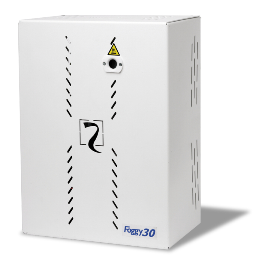
FOGGY 30
FOGGY 30
FOGGY 30
FOGGY 30
FOGGY 30
FOGGY 50
FOGGY 50
FOGGY 50
FOGGY 50
FOGGY 50
SISTEMA DI QUALITA'
CERTIFICATO
UNI EN ISO 9001:2008
IST0813V1.1
- 1 -
I
T
A
E
N
G
F
R
A
Advertisement

Related Manuals for AVS Electronics FOGGY 30


Summary of Contents for AVS Electronics FOGGY 30
- Page 1 GENERA GENERA T T T T T ORI DI NEBBIA ORI DI NEBBIA ORI DI NEBBIA ORI DI NEBBIA GENERA GENERA ORI DI NEBBIA FOGGY 30 FOGGY 30 FOGGY 30 FOGGY 30 FOGGY 30 FOGGY 50 FOGGY 50 FOGGY 50...
- Page 2 Caratteristiche tecniche • ’ ’ 0 i t t ³ • ’ ’ 0 i t t ³ • ’ ’ 0 i t t ³ • ’ ’ 0 i t t ³ • ’ ’ 0 i t t ³...
- Page 3 FORARE QUI FORARE QUI ALTO (installazione verticale a parete) Per il posizionamento del Foggy 30, sia a LATO SINISTRO (installazione orizzontale a parete) parete che a soffitto,utilizzare la dima di foratura a corredo. Segnare i fori in base al...
- Page 4 Punti di fissaggio Utilizzare tasselli in grado di sopportare un peso di almeno 75 Kg Una volta fissato Foggy 30 a soffitto con i tasselli, ruotare i due ganci con occhilo aperto in modo da non ostruire la chiusura del coperchio...
- Page 5 Collegamenti esterni FOGGY 30 Inserire un interruttore di rete onnipolare avente una distanza minima fra i contatti di almeno 3 mm nell’installazione elettrica dell’edificio. Per l’ingresso alimentazione rete elettrica, usare cavi a doppio isolamento. Entrata per collegamento alimentazione di rete...
- Page 6 Dip Switch a l l a l l i l i a l l è a l l è i l i i l i ³ ³ ³ ³ ³ ³ ³ ³ ³ ³ ³ ³ ³ ³ ³ a ’...
- Page 7 XGSM Con la scheda XGSM (opzionale) è possibile, tramite SMS, inviare comandi e ricevere informazioni sullo stato del FOGGY (dalla versione 2.0), inoltre è possibile interagire da remoto tramite FOG SYSTEM per visualizzarne lo stato e programmarne alcuni parametri di funzionamento. Caratteristiche tecniche e l l : i n...
- Page 8 Batteria Alla prima installazione le 2 batterie da 12V - 1,2Ah in dotazione risultano scollegate. Collegare il cavo al FOGGY 50 FOGGY 30 polo positivo libero della batteria indica- Per il cambio del- Per il cambio to in figura.
- Page 9 Curtarolo (Padova) Italy www.avselectronics.com INTEGRATION FOG GENERA FOG GENERA T T T T T OR FOG GENERA FOG GENERA FOG GENERA FOGGY 30 FOGGY 30 FOGGY 30 FOGGY 30 FOGGY 30 FOGGY 50 FOGGY 50 FOGGY 50 FOGGY 50 FOGGY 50...
- Page 10 Technical features • ’ ’ 0 v i t i t a ³ • ’ ’ 0 v i t i t a ³ • ’ ’ 0 v i t i t a ³ • ’ ’ 0 v i t i t a ³...
- Page 11 FORARE QUI FORARE QUI ALTO (installazione verticale a parete) For correct positioning of FOGGY 30 either LATO SINISTRO (installazione orizzontale a parete) at wall or at roof, use the drilling plan supplied. Mark the holes according to preferred...
- Page 12 To made easy the cabling and roof mounting it is possible, using appropriate eyelets, to hang the Foggy 30 on two hook fixing plugs Fixing points Use fixing plugs rated for 75Kg or more After fixing the equipment to the roof with proper plugs, rotate the two hooks in order to enhance the placement of the front cover.
- Page 13 Outdoor connections Insert an omnipolar network switch having a minimum distance between the contacts of at least 3 mm in the electrical installation of the building. For electric network power supply input, use double insulation cables. Input for network power supply connection Input for connecting to the activation system...
- Page 14 Dip Switch ³ l i t ³ ³ ³ ³ ³ ³ ³ ³ ³ ³ ³ ³ ³ : l i Firmware update It is possible to update equipment firmware carrying out the following procedure: Bring DIP 10 to ON to activate buzzer operation Bring DIP 8 to ON Press the RESET button, the buzzer goes off for a few seconds and then shuts off After about ten seconds, as soon as the buzzer goes off again, bring DIP 8 to OFF...
-
Page 15: Installation
XGSM Using the XGSM module (optional) it is possible to send commends and receive status information from the FOGGY via SMS messages (from version 2.0), in addition it is possible to remotely interact with the equipment to monitor the status and to change some functionning parameters Technical characteristics o i t... - Page 16 Battery During the first installation the 2 12V - 1,2Ah batteries supplied are disconnected. FOGGY 50 Connect the cable to the FOGGY 30 available positive pole of In order to change the battery indicated in To replace batteries, figure.
- Page 17 Curtarolo (Padova) Italy www.avselectronics.com INTÉGRATION GÉNÉRATEUR DE BROUILLARD FOGGY 30 FOGGY 30 FOGGY 30 FOGGY 30 FOGGY 30 FOGGY 50 FOGGY 50 FOGGY 50 FOGGY 50 FOGGY 50 SYSTÈME DE QUALITÉ CERTIFIÉ UNI EN ISO 9001:2008 IST0813V1.1 - 17 -...
- Page 18 Caractéristiques techniques • ' ' 0 ' d ' v i t i t a ³ m • ' ' 0 ' d ' v i t i t a ³ m • ' ' 0 ' d ' v i t i t a ³...
- Page 19 FORARE QUI FORARE QUI ALTO (installazione verticale a parete) Pour positionner le Foggy 30, soit au mur soit LATO SINISTRO (installazione orizzontale a parete) au plafond, utiliser le gabarit de perçage fourni. Marquer les trous selon le type PARETE / SOFFITTO/CONTROSOFFITTO : (A) d’installation préétablie, en prenant comme...
- Page 20 Utiliser des chevilles en mesure de supporter un poids d’au moins 75 Kg. Une fois que le Foggy 30 a été fixé au plafond au moyen des chevilles, tourner les deux crochets avec l’œillet ouvert de manière à ne pas obstruer la fermeture du couvercle.
- Page 21 Connexions esternes FOGGY 30 Placer un interrupteur électrique omnipolaire présentant une distance minimale entre les contacts de 3 mm minimum sur l’installation électrique du bâtiment. Pour l’entrée alimentation réseau électrique, utiliser des câbles à double isolation. Entrée pour le branchement alimentation 220 Vac Entrée pour le branchement...
- Page 22 Dip Switch l l i é r i l a é r t é ' è t é r i l a é r t é ' è t é r f i t i l a é r é r f i t i l a é...
- Page 23 XGSM Grâce à la carte XGSM (en option) il est possible, avec un SMS, d’envoyer des commandes et de recevoir des informations sur l’état du FOGGY (à partir de la version 2.0) ; il est en outre possible d’interagir à distance FWIN pour en visualiser l’état et en programmer certains paramètres de fonctionnement.
- Page 24 Batterie À la 1 ère installation, les 2 batteries de 12 V – 1,2 Ah sont débranchées. Brancher le câble sur FOGGY 50 FOGGY 30 la borne positif libre de la batterie indiqué sur Pour l’échange Pour changer le dessin.
Need help?
Do you have a question about the FOGGY 30 and is the answer not in the manual?
Questions and answers