Advertisement
Available languages
Available languages
Quick Links
Curtarolo (Padova) Italy
www.avselectronics.com
FOG GENERA
FOG GENERA T T T T T OR
FOG GENERA
FOG GENERA
FOG GENERA
FOGGY 30
FOGGY 30
FOGGY 30
FOGGY 30
FOGGY 30
FOGGY 50
FOGGY 50
FOGGY 50
FOGGY 50
FOGGY 50
CERTIFIED QUALITY
SYSTEM
UNI EN ISO 9001:2008
IST0787V3.0
- 31 -
OR
OR
OR
OR
E
N
G
Advertisement

Related Manuals for AVS Electronics FOGGY 30


Summary of Contents for AVS Electronics FOGGY 30
- Page 1 Curtarolo (Padova) Italy www.avselectronics.com FOG GENERA FOG GENERA FOG GENERA T T T T T OR FOG GENERA FOG GENERA FOGGY 30 FOGGY 30 FOGGY 30 FOGGY 30 FOGGY 30 FOGGY 50 FOGGY 50 FOGGY 50 FOGGY 50 FOGGY 50...
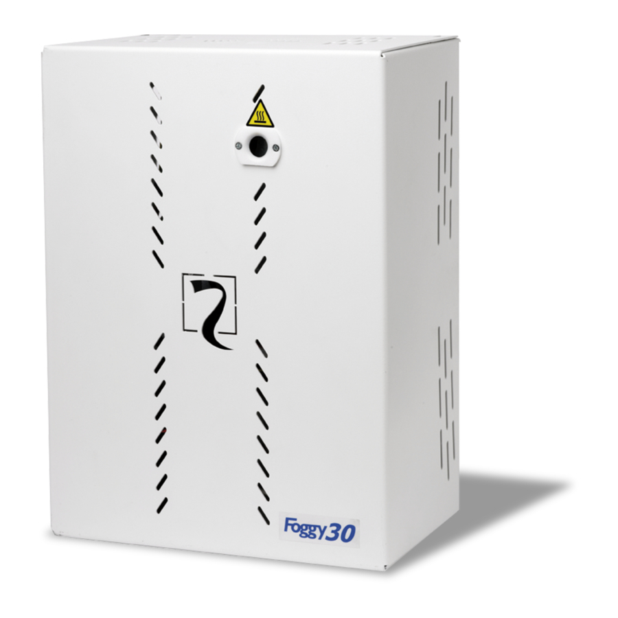
- Page 2 Duration of the fog effect Within at least 10 seconds, Foggy 30 is able to saturate a 100 m³ environment, while Foggy 50, in at least 20 seconds, is able to saturate a 200m³ environment; it will take approximately 20 / 30 minutes to recuperate complete visibility.
- Page 3 Technical features • ’ ’ 0 v i t i t a ³ m • ’ ’ 0 v i t i t a ³ m • ’ ’ 0 v i t i t a ³ m • ’ ’ 0 v i t i t a ³...
- Page 4 Installation Foggy can be installed both on the wall and on the ceiling. Its installation is simplified thanks to a support bracket that the central block of the fog generator is attached to and a pulley (optional KIT MOD.LFT) that makes a ceiling installation easier. In order to lessen the aesthetic impact, Foggy can also be installed inside drop ceilings or wall cupboards, as long as sufficient aeration is guaranteed in order to disburse the heat and a small opening is left in correspondence of the nozzle in order to allow the fog spray to come out.
- Page 5 Warnings For a correct deployment, make sure that there are no obstacles between the FOGGY and the area to protect FOGGY must be installed installed in a way that guarantees minimum covering of the object to be protected Install FOGGY in positions where they cannot be reached in order to avoid possible tampering. During deployment, FOGGY must keep the escape routes visible.
- Page 6 FORARE QUI FORARE QUI ALTO (installazione verticale a parete) For correct positioning of FOGGY 30 either LATO SINISTRO (installazione orizzontale a parete) at wall or at roof, use the drilling plan supplied. Mark the holes according to preferred...
- Page 7 To made easy the cabling and roof mounting it is possible, using appropriate eyelets, to hang the Foggy 30 on two hook fixing plugs Fixing points Use fixing plugs rated for 75Kg or more After fixing the equipment to the roof with proper plugs, rotate the two hooks in order to enhance the placement of the front cover.
- Page 8 Outdoor connections FOGGY 30 Insert an omnipolar network switch having a minimum distance between the contacts of at least 3 mm in the electrical installation of the building. For electric network power supply input, use double insulation cables. Input for network power...
- Page 9 Installation FOGGY 50 Once the Foggy has been removed from the packaging, remove the 4 M4x6 type fixing screws and remove the cover. Verify that package has been positioned in the correct direction before opening the package. Disconnect the cable of the Liquid Sensor from the F.
- Page 10 Outdoor connections Insert an omnipolar network switch having a minimum distance between the contacts of at least 3 mm in the electrical installation of the building. For electric network power supply input, use double insulation cables. Input for network power supply connection Input for connecting to the activation system...
-
Page 11: Alarm Control
Adhesive labels As recommended in the example figure, in proximity of access points to rooms protected by Foggy, locate the ideal position where the adhesive warning label (supplied), as obliged by European Directive 92/58/EEC, at a minimum visual distance of 9 metres. Connection layout CENTRALE CENTRALE... - Page 12 Board RESET BUZZER 1 2 3 4 5 6 7 8 - A + P - P + S - S + D - D + F - F DA DB 12 V PRIM DISABLE FIRE RS485 FAULT FLUID SMOKE TAMPER Terminal board a i l...
- Page 13 Terminal board i t a t i ; v i t l l a s f f v i t i t a f i ( y l t l t n s t I . s t y l l - i t .
- Page 14 Dip Switch ³ l i t ³ ³ ³ ³ ³ ³ ³ ³ ³ ³ ³ ³ ³ : l i Firmware update It is possible to update equipment firmware carrying out the following procedure: Bring DIP 10 to ON to activate buzzer operation Bring DIP 8 to ON Press the RESET button, the buzzer goes off for a few seconds and then shuts off After about ten seconds, as soon as the buzzer goes off again, bring DIP 8 to OFF...
- Page 15 Remote controls Foggy handles a maximum of 16 remote controls and for each remote control it is possible to singularly enable the 4 combined functions described below: Key 1: Activates smoke dispensation (with system entered by Key 2 or by ARM inlet). •...
- Page 16 XGSM Using the XGSM module (optional) it is possible to send commends and receive status information from the FOGGY via SMS messages (from version 2.0), in addition it is possible to remotely interact with the equipment to monitor the status and to change some functionning parameters Technical characteristics o i t...
- Page 17 Battery During the first installation the 2 12V - 1,2Ah batteries supplied are disconnected. FOGGY 50 Connect the cable to the FOGGY 30 available positive pole of the battery indicated in In order to change To replace batteries, figure.
- Page 18 The tank must be regenerated exclusively by AVS Electronics therefore, in order to avoid having an environment unprotected by Foggy while waiting for a recharge, it is recommended to keep an emergency tank.
- Page 19 Foggy. w before each maintenance intervention on the device, disconnect form the power mains. w AVS Electronics is not liable for damage caused by an incorrect installation or by improper use of the equipment. General precautions w Avoid stopping for long periods of time in fog saturated environments, this may cause an irritation of the mucous membranes of airways and eyes.
- Page 20 Special functions Thanks to the FWIN software, the potential of digital technology can be best exploited from PC. FWIN permits: - Checking: - system state - input state - boiler state - liquid state - faults found - boiler features - SIM credit - historical record with 1000 memorized data complete with date and time - Management:...
- Page 21 Type of connection for management with FWIN software The sensor can be connected to the PC by means of: Serial connection RS232 (not used) USB connection Telephone line (modem) USB connection This type of connection allows connecting the fog-forming unit to the PC by means of the USB port of the FOGGY To make the connection: Select the “USB Connection”...
- Page 22 Level: shows the level of the liquid in the tank and the number of supply operations still possible. Liquid expiry: shows the expiry date of liquid in tank set by AVS Electronics. Operating Mode: displays the set operating mode. LED state: remotization of the 3 LEDs on board FOGGY.
- Page 23 Oscilloscope function This application permits checking the temperature and supply state of FOGGY at graphic level. Time scale: selects the time scale on the vertical axis. Traces to be displayed: enables trace display. White line Œ • Ž Yellow line White line: indicates the current boiler temperature.
- Page 24 Permits setting the date of liquid expiry manually. FOGGY, on midday of the first day of the set month/year, sends a liquid expiry notice TXT to the phone profiles enabled to receive the Liquid event. If Automatic is set, the expiry date is that set by AVS Electronics. - 54 -...
- Page 25 Telephone This menu permits entering up to at most 6 telephone numbers. Events: Each telephone number can be enabled to receive the various selected Events by TXT. Switch-on: Communication of Switch-on/Switch- off of system, generated by ARM Input, Remote Control or TXT message.
- Page 26 - 56 -...
- Page 27 - 57 -...
- Page 28 - 58 -...
- Page 29 - 59 -...
- Page 30 Via Valsugana, 63 35010 (Padua) ITALY Tel. 049 9698 411 / Fax. 049 9698 407 avs@avselectronics.it www.avselectronics.com support@avselectronics.it AVS ELECTRONICS S.p.a. reserves the right to make amendments at any moment and without notice. - 60 -...
- Page 31 Curtarolo (Padova) Italy www.avselectronics.com GÉNÉRATEUR DE BROUILLARD FOGGY 30 FOGGY 30 FOGGY 30 FOGGY 30 FOGGY 30 FOGGY 50 FOGGY 50 FOGGY 50 FOGGY 50 FOGGY 50 SYSTÈME DE QUALITÉ CERTIFIÉ UNI EN ISO 9001:2008 IST0787V3.0 - 61 -...
- Page 32 Durée de l’effet brouillard Foggy 30 sature un espace de 100 m³ en un temps minimum de 10 secondes, alors que Foggy 50 sature en 20 secondes un espace de 200m³ ; la densité du « brouillard » généré est tel, que même en aérant les locaux, il faudra 20/30 minutes pour récupérer une visibilité...
- Page 33 Caractéristiques techniques • ' ' 0 i t c o i t ³ • ' ' 0 i t c o i t ³ • ' ' 0 i t c o i t ³ • ' ' 0 i t c o i t ³...
- Page 34 Installation Foggy peut être installé au mur ou au plafond. Son montage est simplifié par un étrier de support auquel sera accroché le bloc central du générateur de fumée et un kit courroie (KIT optionnel MOD. LFT) qui simplifie l’installation au plafond.
- Page 35 Avertissement Pour une expulsion correcte, s’assurer qu’il n’y ait pas d’obstacle entre FOGGY et la zone à protéger. FOGGY doit être installé de manière à garantir une couverture immédiate de la zone à protéger. Installer FOGGY en position non atteignable pour éviter la possibilité de sabotage. Lors de l’expulsion, FOGGY doit maintenir visible la sortie d’urgence.
- Page 36 FORARE QUI FORARE QUI ALTO (installazione verticale a parete) Pour positionner le Foggy 30, soit au mur soit LATO SINISTRO (installazione orizzontale a parete) au plafond, utiliser le gabarit de perçage fourni. Marquer les trous selon le type PARETE / SOFFITTO/CONTROSOFFITTO : (A) d’installation préétablie, en prenant comme...
- Page 37 Utiliser des chevilles en mesure de supporter un poids d’au moins 75 Kg. Une fois que le Foggy 30 a été fixé au plafond au moyen des chevilles, tourner les deux crochets avec l’œillet ouvert de manière à ne pas obstruer la fermeture du couvercle.
- Page 38 Connexions esternes FOGGY 30 Placer un interrupteur électrique omnipolaire présentant une distance minimale entre les contacts de 3 mm minimum sur l’installation électrique du bâtiment. Pour l’entrée alimentation réseau électrique, utiliser des câbles à double isolation. Entrée pour le branchement alimentation 220 Vac Entrée pour le branchement...
- Page 39 Montage FOGGY 50 Une fois le FOGGY sor- ti du carton, retirer les 4 vis de fixation type M4X6 et retirer le couvercle. Vérifier d’avoir positionné le carton dans la direction correcte avant d’ouvrir l’emballage. Débrancher le câble du Détecteur liqui- de du connecteur F.SENSOR de la car- te de gestion.
- Page 40 Connexions esternes Placer un interrupteur électrique omnipolaire présentant une distance minimale entre les contacts de 3 mm minimum sur l’installation électrique du bâtiment. Pour l’entrée alimentation réseau électrique, utiliser des câbles à double isolation. Entrée pour le branchement alimentation 220 Vac Entrée pour le branchement système de Mise En Service Branchement réseau...
- Page 41 Étiquette adhésive Comme conseillé dans le dessin ci-contre, à proximité des locaux protégés par FOGGY, situer la position la meilleure où appliquer l’étiquette adhésive d’avertissement (fournie), comme disposé par la Directive Européenne 92/58/ EEC, à une distance maximale visible de 9 mètres. Schéma de branchement CENTRALE CENTRALE...
- Page 42 Carte RESET BUZZER 1 2 3 4 5 6 7 8 9 10 - A + P - P + S - S + D - D 12 V PRIM DISABLE FIRE RS485 FAULT FLUID SMO KE TAMPER Bornes l i t .
- Page 43 Bornes é r à é i l i é r é r é f é i t a é i t c é v e ' l é r è t i t c é é b i l a ' l v i t é...
- Page 44 Dip Switch l l i é r i l a é r t é ' è t é r i l a é r t é ' è t é r f i t i l a é r é r f i t i l a é...
- Page 45 Télécommandes Foggy gère 16 télécommandes au maximum et, pour chaque télécommande, il est possible d’activer spécifiquement les 4 fonctions telles que associées et décrites ci-dessous : Touche 1: active l’activation de la fumée (avec le système Mis en Service par la touche 3 ou par l’entrée ARM) •...
- Page 46 XGSM Grâce à la carte XGSM (en option) il est possible, avec un SMS, d’envoyer des commandes et de recevoir des informations sur l’état du FOGGY (à partir de la version 2.0) ; il est en outre possible d’interagir à distance FWIN pour en visualiser l’état et en programmer certains paramètres de fonctionnement.
- Page 47 Batterie À la 1 ère installation, les 2 batteries de 12 V – 1,2 Ah sont débranchées. Brancher le câble sur FOGGY 50 FOGGY 30 la borne positif libre de la batterie indiqué sur Pour l’échange Pour changer le dessin.
- Page 48 Le réservoir doit être régénéré exclusivement chez AVS ELECTRONICS aussi, pour éviter de voir les environnements couverts par FOGGY non protégés durant les périodes d’attente de la recharge, il est conseillé...
- Page 49 • Avant toute intervention de manutention sur les systèmes de sécurités connectés, activer le blocage général du FOGGY • Avant toute intervention de manutention sur l’appareil, retirer l’alimentation 220 Vac. • AVS ELECTRONICS n’est pas responsable des dommages causés par une installation non correcte ou une utilisation inadéquate de l’appareil.
- Page 50 Fonctions spéciales Les fonctions spéciales du logiciel FWIN permettent d’exploiter à fond le potentiel de la technologie numérique depuis votre ordinateur. FWIN assure les fonctions suivantes : Vérification : état du système état des entrées état de la chaudière état du liquide anomalies détectées caractéristiques de la chaudière crédit SIM...
- Page 51 Type de connexion pour la gestion par logiciel FWIN Le capteur peut être raccordé à l’ordinateur via : Connexion série RS232 (non utilisée) Connexion USB Ligne téléphonique (modem) Connexion USB Ce type de connexion permet de raccorder le générateur de brouillard à...
- Page 52 Niveau : affiche le niveau de liquide présent dans le réservoir et le nombre de débits encore possibles. Expiration liquide : affiche la date d’expiration, programmée par AVS Electronics, du liquide présent dans le réservoir. Mode de fonctionnement : affiche le mode de distribution programmé.
- Page 53 Fonction oscilloscope Cette application permet de vérifier au niveau graphique la température et l’état de débit de FOGGY. Échelle des temps : sélectionne l’échelle des temps sur l’axe des ordonnées. Pistes à afficher : active l’affichage des pistes. Ligne blanche Œ...
- Page 54 Le premier jour du mois/de l’année programmé/e, FOGGY enverra un SMS d’avis d’expiration de liquide aux profils téléphoniques autorisés à la réception de l’événement Liquide. Si la valeur renseignée est Automatique, la date d’échéance est celle programmée par AVS Electronics. - 84 -...
- Page 55 Téléphonique Ce menu permet de saisir jusqu’à 6 numéros de téléphone. Événements: Chaque numéro de téléphone peut être autorisé à recevoir par SMS les différents Événements sélectionnés. Allumage: Communication d’allumage/arrêt de l’installation générés par Entrée ARM, Télécommande ou SMS. Anomalies: Communication des différentes anomalies détectées par FOGGY : Batterie basse/manquante Température chaudière basse/haute...
- Page 56 - 86 -...
- Page 57 - 87 -...
- Page 58 - 88 -...
- Page 59 - 89 -...
- Page 60 Via Valsugana, 63 35010 (Padua) ITALY Tel. 049 9698 411 / Fax. 049 9698 407 avs@avselectronics.it www.avselectronics.com support@avselectronics.it AVS ELECTRONICS S.p.a. se réserve le droit d’apporter des modifications à n’importe quel moment et sans préavis. - 90 -...
Need help?
Do you have a question about the FOGGY 30 and is the answer not in the manual?
Questions and answers