
Related Manuals for LAMBERTI ELEKTRONIK LATHERM SOL MAXIMAL

Summary of Contents for LAMBERTI ELEKTRONIK LATHERM SOL MAXIMAL
- Page 1 Universal controller for solar energy systems with up to two collector arrays and two storage reservoirs COMMISSIONING MANUAL...
-
Page 2: Table Of Contents
Contents Note! Before beginning assembly or installation work, first read this commissioning manual and familiarise yourself with its content in full! The safety instructions and working instructions in the operating manual must also be observed! Take note of the settings which you make, at the respective places provided for this purpose in this commissioning manual and in the operating manual! Contents Product description ..........................4... - Page 3 Contents 10.9. Additional function: yield calculation ....................36 10.10.Additional function: bypass ......................37 10.11.Additional function: external heat exchanger .................. 38 10.12.Additional function: emergency collector switch-off ................ 38 10.13.Additional function: collector safety....................39 10.14.Additional function: storage reservoir safety ................... 39 10.15.Additional function: collector frost protection .................. 39 10.16.Additional function: thermostat, e.g.
-
Page 4: Product Description
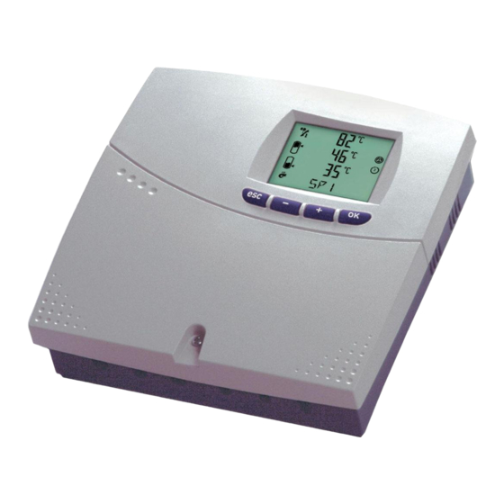
Product description 1. Product description Your solar controller is a microprocessor-based controller, for control of solar energy systems with up to two separate collector arrays and two storage reservoirs. The pumps are controlled so as to optimise the heat energy obtained from the solar collector arrays, according to the solar irradiation and the temperatures which arise in the solar energy system. -
Page 5: Technical Data
Technical data 2. Technical data Supply voltage 230 V AC 50 Hz Power consumption 3.7 VA Fuse 2.5 AT, microfuse 5 mm x 20 mm Inputs 8 inputs: temperature sensor: Pt1000 (-20 °C to +150 °C) volume flow meter: 1 pulse per l (litre) solar sensor: (20 to 1000 W/m²) Outputs 4 semiconductor relays: each 0.5 A, 250 V AC ( ) (20 VA minimum load) -
Page 6: Transport And Storage
Transport and storage 4. Transport and storage Thoroughly check whether the packaging or the controller shows any sign of damage. Transport the controller in the original packaging only. If the controller falls, even from a low height, it may get damaged. Prevent impact and extreme temperatures (below 0 °C or above + 50 °C) during transport and storage. -
Page 7: System Layouts
Installing and connecting the controller 5.2. System layouts Note! Select the system layout which suits your solar energy system and mark it as follows: Layout 3 Layout 2 Schema 1 Layout 1 1 Kollektor / 1 Speicher 1 collector array / 2 storage reservoirs / 1 collector array / 2 storage reservoirs / 1 collector array / 1 storage reservoir / 1 Dreiwegeventil... -
Page 8: Possible Additional Functions
Installing and connecting the controller 5.3. Possible additional functions This table shows you the additional functions which, in principle, are possible in your system layout. Function Described System layout in section Hot water backup heating 10.1. 10.4. Second collector sensor –... -
Page 9: Relay Connector Assignment
Installing and connecting the controller 5.4. Relay connector assignment The following table shows whether the selected additional functions can be realised with your system layout and is to be understood as follows: For the relay assignments shown in the white fields, the relays must be connected exactly as shown in the table. -
Page 10: Sensor Connector Assignment
Installing and connecting the controller 5.5. Sensor connector assignment The following table shows whether the selected additional functions can be realised with your system layout and is to be understood as follows: For the sensor assignments shown in the white fields, the sensors must be connected exactly as shown in the table. -
Page 11: Installing The Controller
Installing and connecting the controller 5.6. Installing the controller Upper fastening hole (for hanging) 140mm Terminal cover Lower fastening holes Choose a suitable installation location. Remove the collector’s terminal cover. Mark and drill (Ø 6 mm) the central upper fastening hole. Insert the provided rawlplug and a screw. Hang the controller on the screw and align it. -
Page 12: Installing The Collector Sensor And Storage Reservoir Sensor
Installing and connecting the controller Electrical connections are to be realised with screw terminals (single wire / fine wire, max. 1.5 mm²). The mains supply’s protective earth connector is to be connected to the 5-pole terminal block ( Protective earth connection of loads (pumps etc.) is to be realised at the 5-pole terminal block provided for this purpose. -
Page 13: Commissioning The Controller
Commissioning the controller 6. Commissioning the controller 6.1. Front view of the controller with buttons and display : Apply current setting Open a submenu On the normal level: Select a submenu Within a menu: Scroll – For settings: Change value : Return to previous menu Discard change and restore previous value Delete input... -
Page 14: The Specialised Mechanic Level
The specialised mechanic level 7. The specialised mechanic level The specialised mechanic level contains the settings which must be set during commissioning (possibly only once). – To open the specialised mechanic level, press and hold the buttons simultaneously for five seconds while in the normal start display. –... -
Page 15: Configuration Of System Layouts
Configuration of system layouts 8. Configuration of system layouts Note! Upon delivery, the configuration is set to layout 1. Changing the system layout causes the factory settings to be restored. All new and changed settings realised beforehand will be lost. –... -
Page 16: System Layout 1 (1 Collector Array, 1 Storage Reservoir, 1 Pump)
Configuration of system layouts 8.1. System layout 1 (1 collector array, 1 storage reservoir, 1 pump) Description of the system layout: The solar controller compares the temperature from collector sensor F1 (TC1) with the temperature from the storage reservoir sensor F4. If the measured temperature difference exceeds the switch-on temperature difference TDE1, which can be set here, the speed-controlled solar pump R1 is switched on and the storage reservoir is loaded. - Page 17 Configuration of system layouts Additional functions: See the overviews in section 5.3. Possible additional functions, section 5.4. Relay connector assignment and section 5.5. Sensor connector assignment. For detailed descriptions of the individual additional functions, see section 10. Setting the additional functions.
-
Page 18: System Layout 2 (1 Collector Array, 2 Storage Reservoirs, 2 Pumps)
Configuration of system layouts 8.2. System layout 2 (1 collector array, 2 storage reservoirs, 2 pumps) Description of the system layout: The solar controller compares the temperature from collector sensor F1 (TC1) with the temperatures from the storage reservoir sensors F4 and F6. If one of the measured temperature differences exceeds one of the switch-on temperature differences set here (TDE1 or TDE2), the corresponding storage reservoir is loaded by means of the respective speed-controlled solar pump... - Page 19 Configuration of system layouts Level Display Function Factory Range Selection setting TDE1 Switch-on temperature 1 K to 20 K E3-2 / 1 difference for storage reservoir 1 between F1 and F4 (not less than switch-off temperature difference + 1 K). TDA1 Switch-off temperature 1 K to 20 K...
-
Page 20: System Layout 3 (1 Collector Array, 2 Storage Reservoirs, 1 Pump, 1 Three-Way Valve)
Configuration of system layouts 8.3. System layout 3 (1 collector array, 2 storage reservoirs, 1 pump, 1 three-way valve) Description of the system layout: The solar controller compares the temperature from collector sensor F1 (TC1) with the temperatures from the storage reservoir sensors F4 and F6. - Page 21 Configuration of system layouts Level Display Function Factory Range Selection setting TDE1 Switch-on temperature 1 K to 20 K E3-2 / 1 difference for storage reservoir 1 between F1 and F4 (not less than switch-off temperature difference + 1 K). TDA1 Switch-off temperature 1 K to 20 K...
-
Page 22: System Layout 4 (1 Collector Array, 2 Storage Reservoirs, 1 Pump, 2 Straight-Way Valves)
Configuration of system layouts 8.4. System layout 4 (1 collector array, 2 storage reservoirs, 1 pump, 2 straight-way valves) Description of the system layout: The solar controller compares the temperature from collector sensor F1 (TC1) with the temperatures from the storage reservoir sensors F4 and F6. - Page 23 Configuration of system layouts Level Display Function Factory Range Selection setting TDE1 Switch-on temperature 1 K to 20 K E3-2 / 1 difference for storage reservoir 1 between F1 and F4 (not less than switch-off temperature difference + 1 K). TDA1 Switch-off temperature 1 K to 20 K...
-
Page 24: System Layout 5 (2 Collector Arrays, 1 Storage Reservoir, 2 Pumps)
Configuration of system layouts 8.5. System layout 5 (2 collector arrays, 1 storage reservoir, 2 pumps) Description of the system layout: The solar controller compares the temperatures from collector sensors F1 (TC1) and F2 (TC2) with the temperature from the storage reservoir sensor F4. - Page 25 Configuration of system layouts Level Display Function Factory Range Selection setting OSW2 Maximum switch-on duration for 100% USW2 to 100% E3-2 / 9 solar pump 2. Additional functions: See the overviews in section 5.3. Possible additional functions, section 5.4. Relay connector assignment and section 5.5.
-
Page 26: System Layout 6 (2 Collector Arrays, 2 Storage Reservoirs, 2 Pumps, 2 Straight-Way Valves)
Configuration of system layouts 8.6. System layout 6 (2 collector arrays, 2 storage reservoirs, 2 pumps, 2 straight-way valves) Description of the system layout: The solar controller compares the temperatures from collector sensors F1 (TC1) and F2 (TC2) with the temperatures from the storage reservoir sensors F4 and F6. - Page 27 Configuration of system layouts Level Display Function Factory Range Selection setting TDE1 Switch-on temperature 1 K to 20 K E3-2 / 1 difference for storage reservoir 1 between F1 and F4 (not less than switch-off temperature difference + 1 K). TDA1 Switch-off temperature 1 K to 20 K...
-
Page 28: System Layout 7 (2 Collector Arrays, 2 Storage Reservoirs, 2 Pumps, 1 Three-Way Valve)
Configuration of system layouts 8.7. System layout 7 (2 collector arrays, 2 storage reservoirs, 2 pumps, 1 three-way valve) Description of the system layout: The solar controller compares the temperatures from collector sensors F1 (TC1) and F2 (TC2) with the temperatures from the storage reservoir sensors F4 and F6. - Page 29 Configuration of system layouts Level Display Function Factory Range Selection setting TDE1 Switch-on temperature 1 K to 20 K E3-2 / 1 difference for storage reservoir 1 between F1 and F4 (not less than switch-off temperature difference + 1 K). TDA1 Switch-off temperature 1 K to 20 K...
-
Page 30: Batch Loading, Parallel Loading And Pump Blockage Protection
Batch loading, parallel loading and pump blockage protection Batch loading, parallel loading and pump blockage protection 9.1. Batch loading Either storage reservoir 1 or storage reservoir 2 is prioritised for loading. When the first-priority storage reservoir’s loading preconditions are no longer met, the second-priority storage reservoir is loaded for a definable batch loading time (SLZ, batch loading duration in minutes). -
Page 31: Setting The Additional Functions
Setting the additional functions 10. Setting the additional functions Note! Mark the additional functions which you have selected, as follows: 10.1. Additional function: hot water backup heating Temperature-based and time-based backup heating of storage reservoir 1 or 2 from another energy source. The storage reservoir for which backup heating is to be used, is defined by the setting SNH. -
Page 32: Additional Function: Anti-Legionella
Setting the additional functions 10.2. Additional function: anti-Legionella The overturn pump for the anti-Legionella function is controlled according to temperature (60 °C) and time (switching-time channel 2). If the preconditions for the anti-Legionella function are met, the overturn pump R4 overturns the water in the storage reservoir until a temperature of at least 60 °C has been measured at storage reservoir sensor F4 / F6 for at least 30 minutes. -
Page 33: Additional Function: Heating Support
Setting the additional functions 10.3. Additional function: heating support The storage reservoir supports room heating by increasing the temperature of the heating return line. The solar controller compares the temperature from STX (a storage reservoir sensor which you are to select) with the temperature from heating return sensor F7. -
Page 34: Additional Function: Solar Sensor
Setting the additional functions 10.5. Additional function: solar sensor The solar sensor measures the solar irradiation. If this falls below Solar sensor the minimum solar radiation value SSG, which is set here, the solar energy system is switched off (hysteresis: 20 W/m²). 1 2 3 Solar controller e-Bus... -
Page 35: Additional Function: Low-Flow For Stratified Storage Reservoir
Setting the additional functions 10.7. Additional function: low-flow for stratified storage reservoir Storage reservoir loading already begins when the switch-on temperature difference TDE is exceeded. The loading pump is operated at the minimum speed USW until the set collector temperature TCS is exceeded, at which point speed control begins. -
Page 36: Additional Function: Yield Calculation
Setting the additional functions 10.9. Additional function: yield calculation The yield of the solar energy system can be calculated with or without a volume flow meter: For yield calculation without a volume flow meter, the control value USW, which represents the loading pump’s minimum speed, must be set to 100%. -
Page 37: Additional Function: Bypass
Setting the additional functions 10.10. Additional function: bypass If the switch-on temperature difference TDE4 between F8 and F4 / F6 is reached, the switching valve (bypass valve) R3 / R4 switches on and the storage reservoir is loaded. (F3) Additional function is shown with system layout 1 Level Display Function... -
Page 38: Additional Function: External Heat Exchanger
Setting the additional functions 10.11. Additional function: external heat exchanger If the switch-on temperature difference TDE4 between F8 and F4 / F6 is reached, the heat exchanger pump R3 / R4 switches on and the storage reservoir is loaded. (F3) Additional function is shown with system layout 1 Level Display... -
Page 39: Additional Function: Collector Safety
Setting the additional functions 10.13. Additional function: collector safety If the collector temperature exceeds the maximum value TCM (which is set here), all storage reservoirs shall be loaded until the emergency storage reservoir switch-off temperature is reached (fixed value: 90 °C). Level Display Function... -
Page 40: Additional Function: Thermostat, E.g. For Activation Of The Circulation Pump
Setting the additional functions 10.16. Additional function: thermostat, e.g. for activation of the circulation pump This function is controlled via switching-time channel 4. If no switching time is set for this channel, the function is constantly active. The sensor input and relay output (NVR relay also possible) are freely selectable. -
Page 41: Additional Function: Temperature Comparison
Setting the additional functions 10.17. Additional function: temperature comparison Sensor inputs and relay outputs (NVR relay also possible) can be freely selected for an additional temperature comparison function. This function is controlled via switching-time channel 5. If no switching time is set here, the function is constantly active. -
Page 42: Additional Function: Hot Water Overturn In Storage Reservoir
Setting the additional functions 10.18. Additional function: hot water overturn in storage reservoir If the switch-on temperature difference WUH between the hot water connection sensor (e.g. F8) and the upper storage reservoir sensor (e.g. F7) is reached and the hot water temperature at sensor F8 is below the target value + 2 K, the speed-controlled overturn pump R2/3/4 switches on and the upper part of the storage reservoir is overturned. -
Page 43: System Information Menu
System information menu 11. System information menu Here, you can read information about the solar controller and define system settings. Level Display Function Factory Range Selection setting E3-10 / 1 Display of software version. E3-10 / 2 Display of hardware version. E3-10 / 3 Display of circuit board version. -
Page 44: Overview Of All Settings
Overview of all settings 13. Overview of all settings Level Dis- Function Factory Range play setting MAX1 Maximum loading temperature MAX1 for storage 70 °C 10 °C to 90 °C reservoir 1. MAX2 Maximum loading temperature MAX2 for storage 70 °C 10 °C to 90 °C reservoir 2. - Page 45 Overview of all settings Level Dis- Function Factory Range play setting Backup heating temperature difference. End value 1 K to 30 K E3-2 / 5 for storage reservoir reloading. USW1 Minimum switch-on duration for solar pump. 30% to OSW1 E3-2 / 6 OSW1 Maximum switch-on duration for solar pump.
- Page 46 Overview of all settings Level Dis- Function Factory Range play setting Activation of the collector safety function. YES / no E3-6 / 2 Maximum temperature for collector. 90 °C 10 °C to 127 °C E3-6 / 3 Selection of relay for the storage reservoir safety 0 to 4 E3-6 / 4 function.
- Page 47 Overview of all settings Level Dis- Function Factory Range play setting E3-10 / 3 Display of circuit board version. Date and time of the most recent adjustment made E3-10 / 4 on the specialised mechanic level. Date and time of the second-most-recent E3-10 / 5 adjustment made on the specialised mechanic level.
-
Page 48: Relay Test Submenu "Rel
Relay test submenu “REL” 14. Relay test submenu “REL” – To navigate to the submenu for “manual adjustment” of relays, press repeatedly until “REL” appears in the display. Call up the “relay test” sublevel by pressing the button. This causes all outputs (relays) to be switched off! The individual relays are selected by pressing –... -
Page 49: Faults And Troubleshooting
Faults and troubleshooting 16. Faults and troubleshooting If your controller ever ceases to function properly, please check the following points: 1. Power supply: If anything appears in the display, there is no problem with the power supply. If nothing appears in the display, please check the mains voltage and the device fuse. - Page 50 Notes:...
- Page 51 Notes:...
- Page 52 The descriptions, performance specifications and graphics in this manual are non-binding. Subject to technical alterations. This manual may not be duplicated, distributed, altered, passed on, translated into another language or used in any other way, without the express permis- sion of the manufacturer. The content of this manual has been carefully checked.
Need help?
Do you have a question about the LATHERM SOL MAXIMAL and is the answer not in the manual?
Questions and answers