
Subscribe to Our Youtube Channel
Related Manuals for ABB UniGear ZVC


Summary of Contents for ABB UniGear ZVC
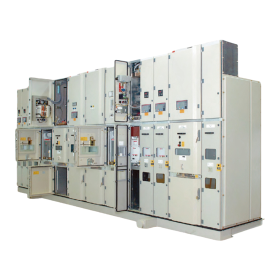
- Page 1 — Medium voltage products UniGear ZVC Installation, operation and maintenance instruction manual • Safety • Reliability • Flexibility • Economy...
-
Page 3: Table Of Contents
— Table of contents Safety precautions 005 – 006 Description 007 – 008 Technical data 009 – 020 Panel design and equipment 021 – 022 Dispatch and storage 023 – 036 Assembly of switchgear at site 037 – 043 Operation of the switchgear Commissioning 045 –... -
Page 4: Safety Precautions
If you have any further questions about this sheet before installing, operating and maintaining instruction manual, the members of our field your UniGear ZVC. For safe operation the organization will be pleased to provide the appropriate Chinese or International Standards required information. -
Page 5: Description
UniGear ZVC switchgear. In each case the order-related data from ABB must be taken into account. - Page 6 U N I G E A R Z V C M E D I U M V O L T A G E P R O D U C T S — Note: 1, 0 2/1 Curve for When switchgear is operated in areas with high determination of the altitude factor K in humidity and/or major rapid temperature...
-
Page 7: Technical Data
T E C H N I C A L D A T A — 3 Technical data — 3.1 Electrical data 3/1 Front and side views Rated voltage Rated power frequency withstand voltage peak 20 (32) Rated lightning impulse withstand voltage Rated frequency 50/60 Rated main busbar current... - Page 8 U N I G E A R Z V C M E D I U M V O L T A G E P R O D U C T S Dimension Symbol Height 2200/2400/2595 Width of a basic panel Depth 1304/1554 See configuration table below Height of basic panel...
-
Page 9: Panel Design And Equipment
4 Panel design and equipment 4.1 Basic structure bit key. The truck is moved between ISOLATED The basis for the UniGear ZVC panel is the outgoing and SERVICE position by a racking screw. feeder panel with fused vacuum contactor of a Self-aligning tulip contacts are located in epoxy horizontal withdrawable design. - Page 10 U N I G E A R Z V C M E D I U M V O L T A G E P R O D U C T S — The earthing connection between the withdrawable phase barriers on the cable terminating module. 4/1 Feeder unit - fused contactor and the panel is established by Complex combinations of cable type and size,...
- Page 11 P A N E L D E S I G N A N D E Q U I P M E N T — 4.2 Enclosure and partitioning (4/12) The enclosure is completed: 4/3 Feeder unit - The enclosure and internal partitions of the panels a Above, by top-mounted pressure-relief flaps direct-on-line motor starter with...
- Page 12 U N I G E A R Z V C M E D I U M V O L T A G E P R O D U C T S — The necessary safety measures to counteract The rear wall of busbar compartment A, mounting 4/5 Typical standard the effects of an internal arc fault must be plate with shutters and horizontal partition and...
- Page 13 P A N E L D E S I G N A N D E Q U I P M E N T — 4/7 Typical top chimney arc duct arrangement — 4/8 Switchboard with bolted end cover — 4/9 View into contactor compartment with door open...
- Page 14 U N I G E A R Z V C M E D I U M V O L T A G E P R O D U C T S — 4/10 View inside contactor compartment — 4/11 Lower shutter may be secured with padlock to prevent unauthorized...
- Page 15 • In the SERVICE or ISOLATED positions, the 4/12 Example of operation mechanically latched contactor can only be UniGear ZVC feeder unit 4.3.1 Panel internal interlocking (4/12) switched off manually when no control voltage To prevent hazardous situations and erroneous...
- Page 16 U N I G E A R Z V C M E D I U M V O L T A G E P R O D U C T S 4.3.2 Doors interlocking • Access to the fused contactor racking spindle The panels are equipped with the following can be restricted with a padlock interlocks:...
- Page 17 P A N E L D E S I G N A N D E Q U I P M E N T — 4.5 Interchangeability and coding The load & line side connectors for the 4/13 V7/ZVC Fused contactor are interchangeable. In cases withdrawable portion are moulded into the operating elements where the order documents require the fused...
- Page 18 U N I G E A R Z V C M E D I U M V O L T A G E P R O D U C T S 4.6.1 Versions available 4.6.3 Optional equipment • Electrically held •...
- Page 19 P A N E L D E S I G N A N D E Q U I P M E N T 4.7.3 Transformer feeder 4.7.5 Cable to bus Transformer feeder ZVC Ratings Cable to bus ZVC-CTB Ratings Circuit full load Circuit full load current current Rated frequency...
- Page 20 U N I G E A R Z V C M E D I U M V O L T A G E P R O D U C T S — 4.8 Ith Limiter designs 4.9 Resistance to internal arc faults 4/16 Auxiliary Ith It is an additional safety feature on the top of The switchgear has been successfully tested in...
-
Page 21: Dispatch And Storage
D I S P A T C H A N D S T O R A G E — 5 Dispatch and storage 5.1 Dispatch • Keep an angle of at least 60° from the horizontal At the time of dispatch, the UniGear panels are for the ropes leading to the crane hook factory-assembled, the withdrawable parts are in the SERVICE position, the earthing switch is... - Page 22 U N I G E A R Z V C M E D I U M V O L T A G E P R O D U C T S 5.5.2 Panels with seaworthy or similar packing Caution! with internal protective sheeting The contactor truck must be handled as •...
-
Page 23: Assembly Of Switchgear At Site
• When the floor top covering is applied, carefully data supplied by ABB must always be taken into backfill the floor frame, leaving no gaps account. • The floor frame must not be subjected to any harmful impact or pressures, particularly during 6.2.1 Metal floor frame/plinth fixing system... - Page 24 U N I G E A R Z V C M E D I U M V O L T A G E P R O D U C T S — Barge cap. 6/1 Typical floor Apex 3747 frame/plinth for UniGear ZVC and ZS1 switchboard. Switchboard holding down bolts Ceiling level 3371 to be spotted through and drilled and tapped on site.
- Page 25 A S S E M B L Y O F S W I T C H G E A R A T S I T E — 6/2 Typical floor plan drawing which Power cables Power cables bottom entry is applicable for bottom entry 1304 mm depth panel, Front...
- Page 26 U N I G E A R Z V C M E D I U M V O L T A G E P R O D U C T S — 6.2.2 Anchoring systems 6.2.3 Fixing with anchoring bolts to concrete 6/6 Anchoring bolt The switchboard can be fixed either to the floor:...
- Page 27 A S S E M B L Y O F S W I T C H G E A R A T S I T E — 6.2.4 Fixing with anchoring bolts to floor frames • Remove the lifting lugs after the panels are in 6/9 After The floor frames, which can be supplied on their final position.
- Page 28 U N I G E A R Z V C M E D I U M V O L T A G E P R O D U C T S — Refer to 6/11 for the hardware details and tightening torque. 6/11 Cubicle joining hardware Cubicles joining hardware...
- Page 29 A S S E M B L Y O F S W I T C H G E A R A T S I T E — 6.5 Install busbars 3150 A…4000 A Busbar 6/12 Typical Clean any greasy or sticky substance off the 2x (D100/12 copper bar) installation of the busbars...
- Page 30 U N I G E A R Z V C M E D I U M V O L T A G E P R O D U C T S — 3150 A…4000 A Busbar 6/14 3150 A 2x (D100/12 copper bar) ……4000 A Busbar arrangement —...
- Page 31 A S S E M B L Y O F S W I T C H G E A R A T S I T E — 1250 A Busbar 6/16 1250 A Busbar 1x (80x10 mm round edge copper bar) arrangement Copper spacer not required M10x35 mm high tensile hexagon socket head screw...
- Page 32 U N I G E A R Z V C M E D I U M V O L T A G E P R O D U C T S — Any tightening torques which deviate from necessary to inspect tightness of busbar 6/17 Typical those in the general recommendation above connections regularly.
- Page 33 A S S E M B L Y O F S W I T C H G E A R A T S I T E — 6.7 Control cable connection • Fasten the control cables at the top end of 6/18 Front bottom The control cables are conveyed into the panel the duct, strip the insulation and convey...
- Page 34 U N I G E A R Z V C M E D I U M V O L T A G E P R O D U C T S — 6.8 Power cable connection 6/20 View with The standard method for entry of power cables optional surge arrestor, capacitive in the switchgear is shown in 6/20 and 6/21.
- Page 35 A S S E M B L Y O F S W I T C H G E A R A T S I T E — A top rear entry power cable with gas duct is It is possible to place three fixed mounted surge 6/22 View with top also available as shown in 6/22.
- Page 36 U N I G E A R Z V C M E D I U M V O L T A G E P R O D U C T S Important note! 6.11 Erection check list Connection with three-core plastic •...
-
Page 37: Operation Of The Switchgear
O P E R A T I O N O F T H E S W I T C H G E A R — 7 Operation of the switchgear — Note on safety at work! 7.1.1 Withdrawable fused contactor 7/1 Operation of The relative work and operating Switching of the contactor is carried out via the... - Page 38 U N I G E A R Z V C M E D I U M V O L T A G E P R O D U C T S — To rack the contactor truck from ISOLATED • The padlock is removed from the blocking 7/2 Racking of position into SERVICE position ensure the plate covering the racking hole.
- Page 39 O P E R A T I O N O F T H E S W I T C H G E A R — Where a voltage transformer (installed on the 7/3 Operating contactor truck) powers the control circuit, please contactor truck label note that this supply is active only when the...
- Page 40 U N I G E A R Z V C M E D I U M V O L T A G E P R O D U C T S — 7.1.3 Racking from IN SERVICE to ISOLATED • Insert the double-bit key (7/5), press inwards 7/6 Service trolley position and turn counter- clockwise against the stop...
- Page 41 O P E R A T I O N O F T H E S W I T C H G E A R — 7.1.4 Vacuum contactor – V7/ZVC The mechanical position indicator will show 7/7 Position indicator ‘ISOLATED’ in white letters on a green The V7/ZVC vacuum contactor is ideal for background.
- Page 42 U N I G E A R Z V C M E D I U M V O L T A G E P R O D U C T S — 7.1.5 Earthing switch – type ZVCE7 • Observe the mechanical/electrical switch 7/8 Shutter The earthing switch - type ZVCE7 - has a snap position indicator...
- Page 43 O P E R A T I O N O F T H E S W I T C H G E A R — If the panels are equipped with capacitive • Isolate and secure the working area in 7/9 Voltage insulators, checking the off-circuit condition accordance with the IEC safety regulations...
-
Page 44: Commissioning
For manufacturer’s recommendation of test scope • Switch the auxiliary and control voltage on and method please contact ABB’s Service • Carry out testing operations on switching Department. devices manually or by electrical control, and... -
Page 45: Maintenance
The checks listed below must be carried This method is based on scheduled activities performed on the out-of-service equipment out by ABB personnel or suitably including: visual checks, apparatus cleaning, qualified client staff. mechanical components lubrication, worn parts replacement and routine tests. - Page 46 1 minute. If there is a discharge during the test, the interrupter must be replaced since this phenomenon means a deterioration in the degree of vacuum. If necessary, contact ABB service. Erosion of the interrupter contacts 3 years or 100,000 Refer to section 9.2.2 below.
- Page 47 In case of need, contact ABB Service. • Check all switchgear accessories and auxiliary devices (e.g. storage batteries) Should this test also be positive, it is reasonable •...
- Page 48 Scotch-Brite, and clean case of faults, they must therefore be serviced loosely adhering particles with a dry, or completely replaced by ABB certified technicians. non-fraying cloth. Next treat the cleaned parts with zinc spray or zinc powder paint 9.4.3 Replacement of parts...
- Page 49 M A I N T E N A N C E — 9.4.3.3 Fuse replacement V7/ZVC 9.4.3.4 Racking blocking coil replacement for 9/4 Fuses module If a fuse is blown we recommend that all fuses V7/ZVC — 9/5 ZVC racking on the truck are replaced.
- Page 50 U N I G E A R Z V C M E D I U M V O L T A G E P R O D U C T S — Rectifier 9/6 ZVC racking blocking coil replacement 2 of 2 6.
- Page 51 M A I N T E N A N C E — 9.5 Spares, auxiliary material and lubricants 9.5.2 Auxiliary materials, lubricants 9/4 Fuses module 9.5.1 Spare parts Lubricant: Isoflex Topas NB 52 — 9/5 ZVC racking A spare parts list is available on request for blocking coil procurement of spare parts.
-
Page 52: Troubleshooting
U N I G E A R Z V C M E D I U M V O L T A G E P R O D U C T S — 10 Troubleshooting — 10.1 Truck cannot enter cubicle. 10.3 Truck cannot be racked in. - Page 53 SERVICE position. Switch the contactor OFF. 10.5.6 Open circuit close coil. Contact ABB to replace close coil. Open the panel first door in accordance with the 10.6 Earth switch cannot be closed. site safety procedures.
-
Page 54: Environmental Protection
Raw material Recommended method of disposal End of life of product Metal material Separation and recycling ABB is committed to complying with the Thermoplastics Recycling or disposal relevant legal and other requirements for Epoxy resin Separation of metal material &... - Page 56 No.885, FangShanXiEr Road, Xiang'an District, Xiamen, Fujian, 361101 Tel: 0592 602 6033 Fax: 0592 603 0505 ABB China Customer Service Hot Line: TEL: 800-820-9696 / 400-820-9696 mail: cn-ep-hotline@abb.com www.abb.com © Copyright 2018 ABB. All rights reserved. Specifications subject to change without notice.
Need help?
Do you have a question about the UniGear ZVC and is the answer not in the manual?
Questions and answers