
Related Manuals for SDMO VERSO 50

Summary of Contents for SDMO VERSO 50
- Page 1 VERSO 50 Instructions Manual 33502027401_3_1 Release: 1.0.27 VERSO 50_v1.0.27_EN 33502027401_3_1 page 1/24...
- Page 2 VERSO 50_v1.0.27_EN 33502027401_3_1 page 2/24...
- Page 3 Index OVERVIEW - MAIN CHARACTERISTICS - INSTALLATION - WIRING ................ 2 1- GENERAL REQUIREMENTS AND INSTALLATION ....................3 1- 1 General notes ..................................3 1- 2 Product Label and Rating plate ............................3 1- 3 Hardware ratings .................................. 4 1- 4 Electrical Installations ................................5 1- 5 Connections ..................................
- Page 4 OVERVIEW - MAIN CHARACTERISTICS - INSTALLATION - WIRING Complete delivered equipment with connecting cables Protection degree: IP20 References ‐ Sizes and Weights: ATS type reference height (mm) width (mm) depth (mm) weight (kg) single phase 40A (see 3-1 page 20/24) 31614298804NE single phase 100A (see 3-2 page 21/24) 31614298904NE...
- Page 5 1- GENERAL REQUIREMENTS AND INSTALLATION 1- 1 General notes WARNING! • Carefully read the manual before the installation or use. • This equipment is to be installed by qualified personnel, complying to current standards, to avoid damages or safety hazards. •...
- Page 6 1- 3 Hardware ratings GENERAL CHARACTERISTICS Rated Vdc voltage 12Vdc (24Vdc) Vdc range From 7Vdc to 33Vdc Rated Vac voltage 400 Vac Vac range Up to 500 Vac Frequency range From 45 to 75 Hz Fixed consumption with backlight 250 mA -30 °C + 70 °C (electric) Temperature range -30 °C + 70 °C (display)
- Page 7 Warning! Before inserting the plugs and supply the board, make sure that the connections strictly comply with the wiring diagram below. 1.8 1.7 1.6 1.5 2.1 2.2 2.3 2.4 VERSO 50 RELAY REMOTE START NOTE: The remote start output is a positive. If you want to use a negative instead of a positive, it’s possible to use an external relay as shown in the electrical drawing.
- Page 8 1- 5 Connections J1 – Genset AC voltage and contactors 1.1 - Mains contactor output (NC) 1.2 - Mains contactor output (NC) 1.3 - Genset contactor output (NO) 1.4 - Genset contactor output (NO) 1.5 - Genset voltage phase 1 1.6 - Genset voltage phase 2 1.7 - Genset voltage phase 3 1.8 - Neutral...
- Page 9 You can also finish the test manually, pressing again the TEST button. During this type of MAN test, the load At the power on, the VERSO 50 is in manual mode. With the switching can be controlled only by KG and KR buttons, even buttons you can choose the functioning mode you prefer.
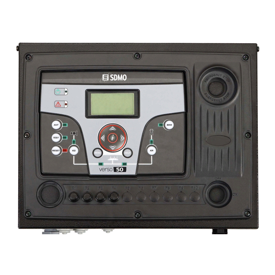
- Page 10 1- 7 Equipment Overview POS. NAME DESCRIPTION Backlighted display that shows all functions, measures and alarms about the generator and Display the mains. Automatically the backlight turns off, and it turns on again when you press a button. Button to select the automatic mode. TEST Button to select the test mode.
- Page 11 1- 8 Display pages 1- 8.4 Generator stats When you turn on the board, you will see the logo page. Then you will be in the stand-by page (Mains). With the left and right arrows, you can move through the different pages. 1- 8.1 Mains A) Maximum value measured on the L1 line voltage of the generator...
- Page 12 1- 8.8 I/O Monitor In this page you can see the state of the input J4.4 (EJPT) and the 3 outputs J1.2 (KR), J1.4 (KG) and J5.4 (Remote start output). 1- 8.9 Info page This page contains the contacts data of the manufacturer – web address, telephone number and address.
- Page 13 2- PROGRAMMATION MENUS 2- 1 Navigation instructions Entering global setup, pressing the MENU button, you have to insert the correct password to access to the programmation menu. The password, by default, is 809. If you enter the wrong password, you will see the indication “wrong code” and you will not be able to enter inside the menu.
- Page 14 0-100 [%] considered faulty and VERSO 50 activates the remote start output (in automatic mode). You can set a delay time for the closure of the mains contactor. This time starts from when the VERSO 50 KR delay 0-100 [s] opens...
- Page 15 “ON Alarms delay” must be at least 5 seconds higher than the preheat time set in the engine protection controller. The cooling procedure is managed by the VERSO 50. If the engine protection controller allows to set a cooling procedure, we advise to disable it and maintain active only the procedure on the VERSO 50 controller.
- Page 16 2- 4 M3 - Test setup DEFAULT POS. NAME DESCRIPTION RANGE OF VALUES SETTINGS Enable test 1 Used to enable or disable the automatic test. On-Off Test type To set the type of test. Daily-Weekly-Monthly Weekly If the type of test is chosen weekly, it permits to set the Mond., Tuesd., Wed., Day of week Thur.
- Page 17 Off-250 [s] the standby page (Mains 1) if no buttons are pressed. Contrast To set the display contrast preferred for the VERSO 50. It is the time of the cyclic indication of the active alarms. The Cyclic alarms 0-255 [s] new parameter is active at the next system startup.
- Page 18 2- 5.3 M4.3 - Security setup The security setup menu permits to enter 6 access codes the permit to lock/unlock the programmation menus. By default, the 6 access codes are set correctly, so you can access to all the menus. You have the possibility to protect the programmation menus entering wrong codes: this way the menus correspondant to the wrong codes inserted are locked.
- Page 19 2- 6 M5 - Alarms list You will see a general screen for the setup of the alarms, composed by 4 pages. In the first page, select and confirm the parameter “a” to choose the code of the alarm. In the upper part of the screen you will see the name of the correspondant alarm. Then modify the parameters from “d”...
- Page 20 Alarm relay Activation Type of stop Alarm code Alarm name 1201 Low frequency generator 1202 High frequency generator 1203 Low voltage generator ...
- Page 21 0-59 [min] before the opening of KR and the closure of KG. EJPT 2 input Function disabled in the VERSO 50 with only 1 input. On/Off If ON, when EJPT mode is active (remote start input active), the No KR with EJPT mains contactor opens and it’s not possible to close it also if the...
- Page 22 3- PANELS - ELECTRICAL DRAWINGS 3-1 Single Phase - 40A VERSO 50_v1.0.27_EN.doc 33502027401_3_1 Page 20/24...
- Page 23 3- 2 Single Phase - 100A VERSO 50_v1.0.27_EN.doc 33502027401_3_1 Page 21/24...
- Page 24 3- 3 Three Phase - 25A VERSO 50_v1.0.27_EN.doc 33502027401_3_1 Page 22/24...
Need help?
Do you have a question about the VERSO 50 and is the answer not in the manual?
Questions and answers