
Related Manuals for Ultimate Healthcare Tamora III Advance

Summary of Contents for Ultimate Healthcare Tamora III Advance
- Page 1 Tamora III Advance Dynamic Mattress Replacement System UPRA367803A-3 User Manual Issue 5: 07/01/2021 UPRA367803A-3.UM-5...
- Page 2 Issue 5: 07/01/2021 Page 2 of 28...
-
Page 3: Table Of Contents
Contents Introduction ............................5 Intended Use ............................ 5 2.1 Contraindications ........................5 One in Three ............................ 5 About the Product ..........................5 Symbols and Statements ......................... 7 Important Safety Information ......................8 Technical Specification ........................9 7.1 Pump............................9 7.2 Mattress ........................... 9 Installation and Set-Up........................ - Page 4 16.1 General ..........................21 16.2 Fuse replacement ........................21 16.3 Air filter replacement ......................21 17 EMC Information ..........................22 Issue 5: 07/01/2021 Page 4 of 28...
-
Page 5: Introduction
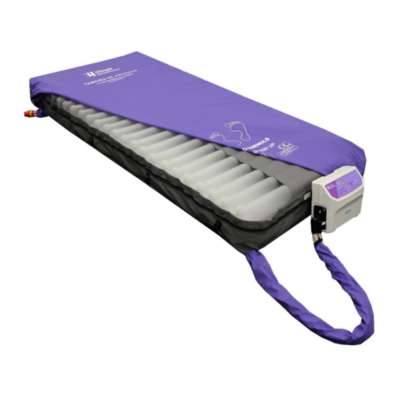
User Manual. Note: Ultimate Healthcare reserves the right to modify the information in this User Manual at any time. The information in this User Manual may vary slightly with respect to the basic design of the product. - Page 6 Mattress Replacement 4 x Static Head Cells (TPU) HEAD END Knitted Cell Retention Bands CPR Valve Removable Cover Figure of 8 cell technology 20 x Alternating Cells (TPU) Cable Management Fixings FOOT END Air Outlet port Issue 5: 07/01/2021 Page 6 of 28...
-
Page 7: Symbols And Statements
Pump Carry Handle Control Panel Swing Out Bed Hooks Air Outlet Port ON/OFF Switch Power Connection 5. Symbols and Statements Note: Indicates tips and advice for the correct use of this product. Caution: Indicates correct operating or maintenance procedures in order to prevent damage to or destruction of the product or other property. -
Page 8: Important Safety Information
Use only the cleaning and disinfectant agents recommended in this User Manual. When connecting product after transportation or storage, inspect the power cable visually for any signs of damage. If evident, do not use product and contact Ultimate Healthcare or your local distributor for repair. -
Page 9: Technical Specification
7. Technical Specification Pump Dimensions: 130mm x 320mm x 230mm (D x W x H) Weight: 3.5 kg Alternating cycle time: 10 / 15 / 20 / 25 / 30 mins Output pressure range: 15 to 50mmHg (+/-10%) Power supply: AC 230V 50 Hz Current: 0.12 A... -
Page 10: Installation And Set-Up
8 Installation and Set-Up Setting up mattress Secure the mattress to the moving parts of the bedframe using the securing straps, and when the system is fully inflated it is ready for the patient to be positioned onto the mattress. The mattress is designed to completely replace any existing mattress which may be in use on a bed. -
Page 11: Cable Management System
Cable management system Cable management fixings are located on each side of the mattress underneath the flap of the cover. The mains power cable should be secured through the cable management fixing as follows: Locate each cable management fixing. ... -
Page 12: Control Panel Operation Guide
9 Control Panel Operation Guide The Control Panel of the Pump is used to make adjustments to the mattress and also indicates fault conditions/service requirements. These are either visual (indicator lights) or audible. Comfort Control Buttons Auto-Firm & Indicator Comfort Setting Indicators Operate / Standby Button &... -
Page 13: Comfort Level
Comfort level The Soft and Firm buttons allow carers to adjust pressures within a safe pre-set range to provide patients with enhanced comfort or support whilst maintaining a very good level of protection and therapy. Qualified clinical advice must always be taken before adjusting mattress pressures. -
Page 14: Function Mode Switch
Function mode switch 9.5.1 Alternate Alternating mode is the default mode for the system. Within this mode the mattress will operate in an alternating 1-in-3 cell cycle. The alternating cycle will continue at the selected cycle time until another mode is selected. 9.5.2 Static Pressing the Function Mode Selection button until the Static indicator illuminates puts the system into Static mode. -
Page 15: Alarm Mute
This will maintain the cells in their present state for up to 24 – 48 hours. It is important to restore the Tamora III Advance dynamic replacement mattress as quickly as possible by reconnecting the supply tubes to the Pump. -
Page 16: Alarms Fault Findings
12. Alarms Fault Findings The Tamora III Advance is equipped with audible and visual alarm indicators. These alert the user to the status of the available mains supply and any mattress defect. 12.1 Low pressure alarm Upon detection of low pressure, an audible alarm will be heard and the Low Pressure indicator will illuminate. - Page 17 Table 2: Alert/Error Code Reference Table Priority High Warning Indicator Audible Output Condition of Warning Description Remarks ↓ Code Mode Output Not in System Key Tone from ONCE Key Tone Shutdown Functional Button Power Failure ONCE Power-Off System Shutdown Shutdown Operate or All Indicators ALL LED...
-
Page 18: Troubleshooting
Indicates that system is scheduled for an annual Service indicator remains service. Please contact Ultimate Healthcare or your illuminated local service provider to arrange. If the problem persists, contact Ultimate Healthcare or your local service provider. Issue 5: 07/01/2021 Page 18 of 28... -
Page 19: Cleaning And Decontamination
14.2 Mattress and cover disinfection The Tamora III Advance mattress, mattress cover and air pipe cover can be cleaned using the following simple procedures in accordance with your Local Infection Control Policy: ... -
Page 20: Pump Disinfection
14.3 Pump disinfection The Pump can be cleaned by wiping down with a cloth dampened with hot water at 60 C containing detergent or with sodium hypochlorite (up to 10,000 parts per million available chlorine). 14.4 Cover laundering The mattress cover and air pipe cover can also be machine washed. Mattress covers and air pipe cover should be completely removed prior to laundering. -
Page 21: Service And Maintenance
12 months regardless of product usage. The Tamora III Advance features a dedicated Annual Service indicator on the control panel which will illuminate and stay ON to alert nursing staff of the need for the system to be professionally serviced. - Page 22 17 EMC Information Manufacturer’s declaration-electromagnetic emissions The device(s) is intended for use in the electromagnetic environment (for home and professional healthcare) specified below. The customer or the user of the device(s) should assure that it is used in such an environment.
- Page 23 Manufacturer’s declaration-electromagnetic immunity The device(s) is intended for use in the electromagnetic environment (for home and professional healthcare) specified below. The customer or the user of the device(s) should assure that it is used in such an environment. Immunity test IEC 60601 Compliance level Electromagnetic environment-...
- Page 24 Manufacturer’s declaration-electromagnetic immunity The device(s) is intended for use in the electromagnetic environment (for home and professional healthcare) specified below. The customer or the user of the device(s) should assure that it is used in such and environment. Immunity test IEC 60601 test level Compliance level Electromagnetic environment-guidance...
- Page 25 Recommended separation distance between portable and mobile RF communications equipment and the device(s) The device(s) is intended for use in an electromagnetic environment (for home and professional healthcare) in which radiated RF disturbances are controlled. The customer or the user of the device(s) can help prevent electromagnetic interference by maintaining a minimum distance between portable and mobile RF communications equipment (transmitters) and the device(s) as recommended below, according to the maximum output power of the communications equipment.
- Page 26 Manufacturer’s declaration-electromagnetic immunity Test specifications for to RF wireless communications equipment ENCLOSURE PORT IMMUNITY The device(s) is intended for use in the electromagnetic environment (for home and professional healthcare) specified below. The customer or the user of the device(s) should assure that it is used in such an environment. Compliance LEVEL Test...
- Page 27 Notes: Issue 5: 07/01/2021 Page 27 of 28...
- Page 28 Ultimate Healthcare Ltd Calmore Industrial Estate, Nutwood Way, Totton Southampton, Hampshire, SO40 3WW Tel: 0333 321 8996 Fax: 023 8066 2388 Email: info@ultimatehealthcare.co.uk www.ultimatehealthcare.co.uk Issue 5: 07/01/2021 Page 28 of 28...
Need help?
Do you have a question about the Tamora III Advance and is the answer not in the manual?
Questions and answers