Advertisement
INSTRUCTION MANUAL
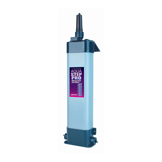
AQUA STEP PRO
UV Sterilizer
15 Watt & 25 Watt Models
Initial Set Up
A.
Screw in plugs on each side of the manifold
Make sure plug "O" rings are seated properly.
The bottom inlet ports will not be needed
in this type of installation. Wrap threads with
thread seal tape. ('O-rings need periodic silicone lubrication).
B.
Wrap thread seal tape on the male threads of one 3/4" MPT x 1/2" barb
B.
Threaded Seal Tape
C.
Screw in the 3/4" MPT x 1/2" barb elbow into top inlet port NOTE the
inlet port is located in front of the UV light indicator.
D.
Screw in the waterfall assembly into the
outlet port located at the top of
the AquaStep PRO.
E.
Slide the rubber gasket
onto the hard quartz
sleeve so that the edge
of the sleeve is visible as
shown below (Fig. F).
F.
Slide the quartz sleeve into the
AquaStep PRO unit.
G.
Screw on the quartz sleeve cap.
Hand tighten only.
H.
Take out the bulb and ballast
from the box. Connect the bulb
to the ballast. Note: there is only
one way to connect the bulb to
the ballast. The four pin
elbow and the waterfall assembly. Wrap each
Threaded Seal Tape
tting 5-7 times with thread seal tape.
Only one 3/4" MPT x 1/2" barb elbow will
be needed for this type of installation.
D.
1
®
C.
Outlet Port
Inlet Port
H.
E.
G.
F.
A.
UV Light
Indicator
I.
Advertisement
Table of Contents

Related Manuals for Lifegard AQUA STEP PRO

Summary of Contents for Lifegard AQUA STEP PRO
- Page 1 INSTRUCTION MANUAL AQUA STEP PRO ® UV Sterilizer 15 Watt & 25 Watt Models Initial Set Up Screw in plugs on each side of the manifold Make sure plug “O” rings are seated properly. The bottom inlet ports will not be needed in this type of installation.
- Page 2 connector on the bulb needs to match the four holes on the ballast end. DO NOT use excessive force or this may damage the parts. Slide the bulb into the quartz sleeve through the quartz cap. Gently push the bulb all the way in. Screw on the splash boot of the ballast connection onto the quartz cap.
- Page 3 B3. Wrap thread seal tape on the Threaded Seal Tape male threads of the two 3/4” MPT x 1/2” barb elbow ttings provided. Wrap each tting 5-7 times with the tape. B4. Screw one 3/4” MPT x 1/2” barb elbow tting into top inlet port.
- Page 4 D2. Screw in the plugs on each side of the bottom manifold. Make sure the plug “O” rings are seated properly. In most cases, the bottom inlet ports will not be needed in this type of installation. In steps D2 and D4, refer to installation drawings in section #B (Beside the Aquarium).
- Page 5 PARTS BREAKDOWN AquaStep 15W & 25W ITEM PART# QTY. DESCRIPTION 1. R175267 1 Ballast Assembly 15/25 Watt 115V 2. R175278 Ballast Assembly 15/25 Watt 230V 1, 2 3. R175235 Splash Boot 4. R175232 Female 4 Pin Connector 5. R175229DP 1 UV Bulb 15 Watt 6.
- Page 6 Typical AquaStep Flow Set-Ups Wattage Bulb Length Recommended Pump Recommended Aquarium Size AquaStep 15W 15.35” QuietOne 1200 or 2200 100 Gallons AquaStep 25W 17.83” QuietOne 2200 or 3000 200 Gallons CustomFlo Water System Sizes and Speci cations: Part # Description Inlet Outlet Ht.
Need help?
Do you have a question about the AQUA STEP PRO and is the answer not in the manual?
Questions and answers