Advertisement
Quick Links
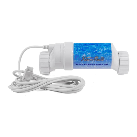
SALT WATER SYSTEM CHLORINATOR
ITEM: 90160 / 90161 / 90162
OWNER'S MANUAL AND SAFETY INSTRUCTIONS
SAVE THIS MANUAL: KEEP THIS MANUAL FOR SAFETY WARNINGS, PRECAUTIONS, ASSEMBLY,
OPERATING, INSPECTION, MAINTENANCE AND CLEANING PROCEDURES. WRITE THE PRODUCT'S
SERIAL NUMBER ON THE BACK OF THE MANUAL NEAR THE ASSEMBLY DIAGRAM (OR MONTH
AND YEAR OF PURCHASE IF PRODUCT HAS NO NUMBER)
FOR QUESTIONS PLEASE CALL OUR CUSTOMER SUPPORT: 909.628.0880 MON-FRI 9AM TO 3PM PST
Advertisement

Related Manuals for Xtreme Power 90160


Summary of Contents for Xtreme Power 90160
- Page 1 SALT WATER SYSTEM CHLORINATOR ITEM: 90160 / 90161 / 90162 OWNER’S MANUAL AND SAFETY INSTRUCTIONS SAVE THIS MANUAL: KEEP THIS MANUAL FOR SAFETY WARNINGS, PRECAUTIONS, ASSEMBLY, OPERATING, INSPECTION, MAINTENANCE AND CLEANING PROCEDURES. WRITE THE PRODUCT’S SERIAL NUMBER ON THE BACK OF THE MANUAL NEAR THE ASSEMBLY DIAGRAM (OR MONTH AND YEAR OF PURCHASE IF PRODUCT HAS NO NUMBER) FOR QUESTIONS PLEASE CALL OUR CUSTOMER SUPPORT: 909.628.0880 MON-FRI 9AM TO 3PM PST...
-
Page 2: Important Safety Information
IMPORTANT SAFETY INFORMATION SAFETY The warnings, precautions, and instructions discussed in this instruction manual cannot cover all possible conditions and situations that may occur. It must be understood by the operator that common sense and caution are factors which cannot be built into this product, but must be supplied by the operator. Read carefully and understand all ASSEMBLY AND OPERATION INSTRUCTIONS before operating. -
Page 3: Operation
OPERATION How to replace CFT Step 1. Turn off the power to the pump and chlorine salt generator. Ideally this should be done at the circuit breaker. The controller display should go blank. Step 2. Relieve the water pressure at the relief valve, it is usually on top of your pool filter. - Page 4 OPERATION Step 7. Place the CFT cell into the piping and screw the unions back onto the ends of the new cell. Tighten the thread. The cell can be positioned either way. In fact, we suggest to reverse the cell every time you clean it to extend the life of the cell.
-
Page 5: Parts List
PARTS LIST 1: THREAD 2: FLOW SWITCH... -
Page 6: Troubleshooting
TROUBLESHOOTING... - Page 7 TROUBLESHOOTING Polaris-Attach wires to proper screw terminals as shown below. Note that screw terminal “1” is marked on the Polaris PCB. TROUBLESHOOTING Diagnostic Displays Sequential pushes of the small “diagnostic” button next to the LCD display will cause the SPS to display the following information: 1.
- Page 8 OF NOTE PLEASE READ THE FOLLOWING CAREFULLY THE MANUFACTURER AND/OR DISTRIBUTOR HAS PROVIDED THE PARTS LIST AND ASSEMBLY DIAGRAM IN THIS MANUAL AS A REFERENCE TOOL ONLY. NEITHER THE MANUFACTURER OR DISTRIBUTOR MAKES ANY REPRESENTATION OR WARRANTY OF ANY KIND TO THE BUYER THAT HE OR SHE IS QUALIFIED TO MAKE ANY REPAIRS TO THE PRODUCT, OR THAT HE OR SHE IS QUALIFIED TO REPLACE ANY PARTS OF THE PRODUCT.