Table of Contents
Advertisement
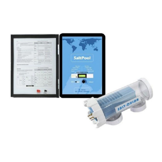
SALT WATER SYSTEM CHLORINATOR
ITEM: 90151 / 90152 / 90153
OWNER'S MANUAL AND SAFETY INSTRUCTIONS
SAVE THIS MANUAL: KEEP THIS MANUAL FOR SAFETY WARNINGS, PRECAUTIONS, ASSEMBLY,
OPERATING, INSPECTION, MAINTENANCE AND CLEANING PROCEDURES. WRITE THE PRODUCT'S
SERIAL NUMBER ON THE BACK OF THE MANUAL NEAR THE ASSEMBLY DIAGRAM (OR MONTH
AND YEAR OF PURCHASE IF PRODUCT HAS NO NUMBER)
FOR QUESTIONS PLEASE CALL OUR CUSTOMER SUPPORT: 909.628.0880 MON-FRI 9AM TO 3PM PST
Advertisement
Table of Contents
Troubleshooting

Related Manuals for Xtreme Power 90151


Summary of Contents for Xtreme Power 90151
- Page 1 SALT WATER SYSTEM CHLORINATOR ITEM: 90151 / 90152 / 90153 OWNER’S MANUAL AND SAFETY INSTRUCTIONS SAVE THIS MANUAL: KEEP THIS MANUAL FOR SAFETY WARNINGS, PRECAUTIONS, ASSEMBLY, OPERATING, INSPECTION, MAINTENANCE AND CLEANING PROCEDURES. WRITE THE PRODUCT’S SERIAL NUMBER ON THE BACK OF THE MANUAL NEAR THE ASSEMBLY DIAGRAM (OR MONTH AND YEAR OF PURCHASE IF PRODUCT HAS NO NUMBER) FOR QUESTIONS PLEASE CALL OUR CUSTOMER SUPPORT: 909.628.0880 MON-FRI 9AM TO 3PM PST...
-
Page 2: Important Safety Information
IMPORTANT SAFETY INFORMATION GENERAL SAFETY WARNINGS Read all safety warnings and instructions. Failure to follow the warnings and instructions may result in electric shock, fire and/or serious injury. Save all warnings and instructions for future reference. SAFETY The warnings, precautions, and instructions discussed in this instruction manual cannot cover all possible conditions and situations that may occur. -
Page 3: Water Chemistry
OPERATION Water Chemistry As with any pool, it is important that you maintain proper water chemistry of the pool water, including pH, alkaline content, and calcium levels. The only special requirement for SPS is to maintain proper levels of salt and stabilizer. It is important to maintain these levels in order to prevent corrosion or scaling and to ensure maximum enjoyment of the pool. -
Page 4: Salt Level
OPERATION HOW TO USE: Measure pool pH, temperature, calcium hardness, and total alkalinity. Use the chart above to determine Ti, Ci,and Ai from your measurements. Insert values of pH, Ti, Ci and Ai into the above equation. If Si equals .2 or more, scaling andstaining may occur. If Si equals -.2 or less corrosion or irritation may occur. Salt Level: Use the chart below to determine the amount of salt needs to be added to reach the recommended levels. - Page 5 APPLICATIONS SALT DOES NOT EVAPORATE FROM POOL The only way to lower the salt concentration is to partially drain the pool and refill with fresh water.
- Page 6 OPERATION STABILIZER (CYANURIC ACID) Always test for stabilizer (cyanuric acid) level, when testing for salt. This test should be done at least once per month. Use the chart below to determine how much stabilizer must be added to raise the level to 80 ppm . POUNDS and (Kg) OF STABILIZER (CYANURIC ACID) NEEDED FOR 80 PPM Gallons and (Liters) of Pool/Spa water POLYMERS:...
-
Page 7: Indicator Led
OPERATION CONTROLS MAIN SWITCH AUTO: For normal operation, the Main switch should be left in the AUTO position. In this position the SPS will produce chlorine according to the “Desired Level %” adjustment setting for the entire filtering / pumping cycle. SUPER CHLORINATE: When you have an abnormally high bather load, heavy rainfall, cloudy water conditions, or any other condition which requires that a large amount of purification be introduced, set the Main Switch in the SUPER CHLORINATE position. -
Page 8: Diagnostic Displays
OPERATION Diagnostic Displays: Sequential pushes of the small “diagnostic” button next to the LCD display will cause the Aqua Rite to display the following information: 1. Pool temperature (xx degrees Fahrenheit or Celsius) 2. Cell voltage (typically 21.0 to 27.0 volts when chlorine is being generated, otherwise 16-25V) 3. -
Page 9: Spring Start-Up
OPERATION Servicing and Cleaning the cell Turn off power to the SPS before removing the CELL. Once removed, look inside the cell and inspect for scale formation (light colored crusty or flaky deposits) on the plates and for any debris that has passed through the filter and gotten caught on the plates. If no deposits are visible, reinstall. -
Page 10: Installation
OPERATION INSTALLATION Installation must be performed in accordance with Local NEC codes. Preparing Pool Water: The pool’s chemistry must be balanced BEFORE activating the SPS. It is recommended that you consult a pool professional for the initial balancing each season. NOTE: At the beginning of each season, add metal remover and polymer based (non copper) algaecide to the pool, per manufacturer’s instructions. - Page 11 OPERATION Electrolytic Cell: Install using the unions provided. Tighten by HAND for a watertight seal. For pool/spa combination systems with spillover, use configurations #2 or #3 above to allow chlorination for both the pool and spa during spillover but preventing over chlorination when operating the spa only.
- Page 12 OPERATION Plumbing Power must be turned off at the circuit breaker before performing any wiring. Be sure to follow Local and NEC electrical codes. To provide safe operation, SPS must be properly grounded and bonded. Input Power for stand-alone operation: Wire the SPS to the LOAD SIDE of the filter pump timer.
- Page 13 OPERATION NOTE: Wire the pump directly to the time clock—do not use the SPS as a junction box. Bonding: A lug used for bonding is attached to the bottom of the SPS enclosure (see diagram below). The SPS must be bonded with an 8 AWG copper wire (6 AWG Canada) to the pool bonding system. Electrolytic Cell and Flow Switch: The electrolytic cell and flow switch cables are terminated with connectors that plug into the SPS for easy attachment and removal.
- Page 14 OPERATION Input power for use with Goldline, Pentair and Polaris controls: Wire the SPS® DIRECTLY TO 120/240vac POWER (not through timer or relay). Optional Goldline, Pentair and Polaris controls: The Goldline, Pentair and Polaris controls use a 4 wire connection to communicate to the SPS and can be wire up to 500’ apart. Any outdoor rated 4 conductor cable can be used.
-
Page 15: Operation And Troubleshooting
OPERATION AND TROUBLESHOOTING Polaris-Attach wires to proper screw terminals as shown below. Note that screw terminal “1” is marked on the Polaris PCB. TROUBLESHOOTING Diagnostic Displays Sequential pushes of the small “diagnostic” button next to the LCD display will cause the SPS to display the following information: 1. - Page 16 OPERATION How to replace CFT Step 1. Turn off the power to the pump and chlorine salt generator. Ideally this should be done at the circuit breaker. The controller display should go blank. Step 2. Relieve the water pressure at the relief valve, it is usually on top of your pool filter.
- Page 17 OPERATION Step 7. Place the CFT cell into the piping and screw the unions back onto the ends of the new cell. Tighten the thread. The cell can be positioned either way. In fact, we suggest to reverse the cell every time you clean it to extend the life of the cell.
-
Page 18: Parts List
PARTS LIST... -
Page 19: Troubleshooting
TROUBLESHOOTING “No Flow” LED illuminated or flashing: The SPS has sensed a no flow condition and has stopped generating chlorine. Check that the flow switch is plugged into the connector on the bottom of the control unit and that the wire is not cut or damaged. Make sure you have at least 12”... -
Page 20: Please Read The Following Carefully
OF NOTE PLEASE READ THE FOLLOWING CAREFULLY THE MANUFACTURER AND/OR DISTRIBUTOR HAS PROVIDED THE PARTS LIST AND ASSEMBLY DIAGRAM IN THIS MANUAL AS A REFERENCE TOOL ONLY. NEITHER THE MANUFACTURER OR DISTRIBUTOR MAKES ANY REPRESENTATION OR WARRANTY OF ANY KIND TO THE BUYER THAT HE OR SHE IS QUALIFIED TO MAKE ANY REPAIRS TO THE PRODUCT, OR THAT HE OR SHE IS QUALIFIED TO REPLACE ANY PARTS OF THE PRODUCT.
Need help?
Do you have a question about the 90151 and is the answer not in the manual?
Questions and answers
Won't come on
The Xtreme Power 90151 may not turn on due to the following reasons:
1. No Input Power – Verify that 120/240 VAC input power is connected to the control.
2. Improper Jumper Settings – Ensure that the jumpers are set correctly.
3. Blown Fuse – Check the 20 amp mini ATO fuse located on the circuit board above the cell connector.
4. Voltage Issue – Use a voltmeter to confirm that input voltage is present.
If input power is available but the unit still does not turn on, replacing the fuse may be necessary.
This answer is automatically generated
@george baker
@Mr. Anderson where is it located
Model A0183