
Related Manuals for Yacht Devices YDOG-01


Summary of Contents for Yacht Devices YDOG-01
- Page 1 User Manual Outboard Gateway YDOG-01 also covers models YDOG-01N, YDOG-01R Firmware version 1.00 2021...
- Page 2 © 2021 Yacht Devices Ltd. Document YDOG-01-001. August 8, 2021. Web: http://www.yachtd.com/ NMEA 2000® is a registered trademark of the National Marine Electronics Association. SeaTalk NG is a registered trademark of Raymarine UK Limited. Garmin® is a registered trademark of Garmin Ltd.
-
Page 3: Table Of Contents
Contents Introduction Warranty and Technical Support I. Specification II. Device Installation and Connection to NMEA 2000 III. Connection to the Engine and Initial Setup IV. LED Signals V. Configuration with a Hidden Button VI. Configuration with Installation Description Strings VII. Firmware Updates Appendix A. -
Page 4: Introduction
Introduction The Outboard Gateway (hereinafter Gateway or Device) is designed for petrol engines without digital interfaces, and provides NMEA 2000 equipment with engine revolutions (RPM), alternator voltage (measured at the NMEA 2000 interface) and engine hours. It can also be programmed to use data from NMEA 2000 temperature or pressure sensors and send these data as coolant and oil pressure or temperature, boost or fuel pressure. -
Page 5: Warranty And Technical Support
Warranty and Technical Support The Device warranty is valid for two years from the date of purchase. If a Device was purchased in a retail store, the sale receipt may be requested when applying for a warranty claim. The Device warranty is terminated in case of violation of the instructions of this Manual, case integrity breach, or repair or modification of the Device without manufacturer’s written permission. -
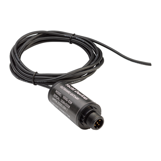
Page 6: Specification
I. Specification Figure 1. Drawing of YDOG-01R (at left) and YDOG-01N (at right) models of Device Our devices are supplied with different types of NMEA 2000 connectors. Models containing an «R» in the suffix of the model name are equipped with Raymarine SeaTalk NG compatible connectors. - Page 7 -50 to +180 °C Weight Yacht Devices Ltd declares that this product is compliant with the essential requirements of EMC directive 2014/30/EU and radio and TTE directive 1999/5/EC. Dispose of this product in accordance with the WEEE Directive. Do not mix electronic waste with domestic or industrial refuse.
-
Page 8: Device Installation And Connection To Nmea 2000
II. Device Installation and Connection to NMEA 2000 The Device requires no maintenance. When deciding where to install the Device, choose a dry mounting location. Do not place the Device where it can be flooded by water or exposed to rain or water spray. Please note that you may need to observe LED signals and/or press the Gateway’s hidden button during the configuration procedure. - Page 9 If your outboard engine is big enough, the Device can be placed inside the engine. Make sure that it is securely fastened, ventilated, isolated from hot surfaces and protected from possible water, oil or petrol spray. If you have a problem with routing the NMEA 2000 cable to the motor, you can place the Outboard Gateway and NMEA 2000 Wi-Fi Gateway YDWG-02 inside the motor, and power them from the ignition.
-
Page 10: Connection To The Engine And Initial Setup
III. Connection to the Engine and Initial Setup Do not electrically connect Device’s wire. The Device’s wire works like an antenna catching ignition impulses sent to a spark plug. Usually you need to wrap the wire 3-5 times around the spark plug wire, and fix the loops with tape (we recommend a tape rated for automotive use). - Page 11 Avoid placing the Device’s wire near voltage regulators, an alternator or other sources of electro-magnetic noise. If the wire is too long, you may cut it. If the wire is too short, you can enlarge it, but note that a longer wire can also catch more noise. If you have a choice between enlarging of NMEA 2000 cable and Device’s wire, it is better to enlarge the NMEA 2000 cable, because it is designed to work in a harsh environment and is less susceptible to electromagnetic interference.
- Page 12 If you have one of our NMEA 2000 gateways, you can observe the incoming signal (500 milliseconds recording, updated twice per second) in the free CAN Log Viewer software (see Section VI). To open the window with oscillograms (Figure 2), click the “More…”...
- Page 13 2. Tuning the signal quality When the signal strength is tuned, check the second LED’s signal. It will be GREEN, if the quality of the signal is good. If the signal is RED, try removing one or two turns (the first signal must remain GREEN, we assume that the signal is overamplified, as at Figure 1.B), or, conversely, try to add one more turn (assuming that signal is amplified not enough amplified, despite the first signal being GREEN).
- Page 14 Both settings can be modified with the hidden button or with PC software (please, refer Sections V and VI). 4. Other settings In case of two or more engines, you should configure the engine number for all engines except the port engine. This can be done with the hidden button or with PC software. If the current engine hours are known, you can specify this number as fixed offset (YD:HOURS command).
-
Page 15: Led Signals
IV. LED Signals The Device is equipped with a bi-color LED that indicates the Device’s state. At power on, the Device produce a single very short GREEN flash to indicate that power is supplied. 1. Signals during normal operation During the normal operation, the Device emits a four-flash sequence every 5 seconds. When the engine is running, you should observe GREEN-GREEN-RED-GREEN or four GREEN flashes. - Page 16 2. Signals during configuration with button The LEDs’ behavior during configuration with the hidden button is described in Section V. 3. Signals during firmware update The LEDs’ behavior during firmware update is described in Section VII. — 16 —...
-
Page 17: Configuration With A Hidden Button
V. Configuration with a Hidden Button With this method, you can change engine number, RPM divider, and pulse counting algorithm, as well as reset the Device to factory settings. The status LED of the Device will constantly shine RED when the hidden button is pressed. - Page 18 All processes are identical to engine number programming. Note that a NMEA 2000 data field is limited to 16383 RPM and with an incorrect divider the data may be unavailable at high revolutions (e.g., you need a divider of 4, but set the divider to 1 and NMEA 2000 data field will have an “out of range”...
-
Page 19: Configuration With Installation Description Strings
VI. Configuration with Installation Description Strings Installation description strings are stored in the Device’s memory and are usually written by installers to specify the device location or to leave notes or contact information. They can be set with a PC software and a hardware gateway to the NMEA 2000 network. - Page 20 Windows, Mac OS X and Linux) at: http://www.yachtd.com/downloads/ A Yacht Devices NMEA 2000 Wi-Fi Gateway, Yacht Devices NMEA 2000 Ethernet Gateway, Yacht Devices NMEA 2000 USB Gateway or Yacht Devices NMEA 2000 Wi-Fi Router is required to connect the PC to the NMEA 2000 network. The CAN Log Viewer also allows you to modify the NMEA 2000 device instance by entering a value in the dedicated field (see «Address Claim»...
- Page 21 1.2 YD:DEV [0..255] Switches NMEA 2000 device’s instance to specified value. This setting is used in large NMEA 2000 networks and does not effect the Device’s behavior. 1.3 YD:SYS [0..15] Switches the NMEA 2000 system instance of the Device to the specified value. This setting is used in large NMEA 2000 networks and does not affect the Device’s behavior.
- Page 22 2. Settings required at initial setup Settings in this group can also be programmed with the hidden button (see Section V). 2.1 YD:ENGINE [0..3] Factory setting is 0 (port or single engine). Set to 1 for starboard engine in twin engines configuration or for middle engine in 3 engines configuration.
- Page 23 Example 1. Set the 1 hour 3 minutes and 30 second offset: YD:HOURS 63.5 3.2 YD:VOLTMETER [-1.25 .. 1.25] Factory setting is 0. Fixed offset for voltage measurements in Volts, can be used to compensate voltage dropout in wires. 3.3 YD:24V [ ON | OFF ] Factory setting is OFF.
- Page 24 Temperature”. In this case, you can use an instance between 1 and 253 to “hide” this sensor from the MFD. For example, to configure the Yacht Devices Digital Thermometer YDTC-13 as a coolant temperature sensor, type the first command in thermometer properties, and the second command in the Gateway’s properties (instance 10 was randomly choosen):...
- Page 25 5. Warnings and indicators 5.1 YD:WARNINGS [ON | OFF] Factory setting is ON. Globally tuns on/off all warnings described below. 5.2 YD:OVERSPEED [50..12700 | OFF] Factory setting is OFF. To turn on the engine speed warning (revolutions exceeded the limit), set the value in the specified range with a step of 50 RPM. 5.3 YD:HIGHTEMP [90..344 | OFF] Factory setting is OFF.
-
Page 26: Firmware Updates
Firmware updates can be done with free CAN Log Viewer software running on Microsoft Windows, Mac OS X and Linux: http://www.yachtd.com/products/can_view.html The program must be connected to an NMEA 2000 network with Yacht Devices NMEA 2000 USB Gateway YDNU-02, Wi-Fi Gateway YDWG-02, Ethernet Gateway YDEN- 02 or Wi-Fi Router YDNR-02. - Page 27 If in doubt, watch the video with the update procedure on our web site. During the firmware upload, the Device’s LED flashes very fast. When the firmware is updated, Devices produce five half-second RED signals and the CAN Log Viewer also informs you that the update is successfully done.
-
Page 28: Appendix A. Troubleshooting
APPENDIX A. Troubleshooting Situation Possible cause and required actions 1. No power supply on the bus. Check if the bus power LED does not signal when NMEA 2000 is is supplied (NMEA 2000 network requires a separate turned on power connection and cannot be powered by a plotter or another Device connected to the network). - Page 29 Table continued Situation Possible cause and required actions 1. Wrong algorithm. See above. 2. The signal is Non-stable RPM overamplified. See the III.2. 3. The power circuit is readings susceptible to EMI. Use proper NMEA 2000 data and power cables and avoid routing near EMI sources. 1.
-
Page 30: Appendix B. Nmea 2000 Messages Supported By Device
APPENDIX B. NMEA 2000 Messages Supported by Device Message Receive Transmit ISO Acknowledgment, PGN 59392 (0xE800) ISO Request, PGN 59904 (0xEA00) ISO Transport Protocol (DT), PGN 60160 (0xEB00) ISO Transport Protocol (CM), PGN 60416 (0xEC00) ISO Address Claim, PGN 60928 (0xEE00) ISO Commanded Address, PGN 65240 (0xFED8) NMEA Group Function, PGN 126208 (0x1ED00) PGN List, PGN 126464 (0x1EE00) - Page 31 Note: 1) NMEA 2000 Device Instance, System Instance, Installation Description Field 1 and Installation Description Field 2 can be changed with PGN 126208 (professional NMEA 2000 installer software and hardware may be required). 2) Periodic transmission intervals can be changed with YD:PGN and YD:ZERO_RPM commands (see Section VI).
Need help?
Do you have a question about the YDOG-01 and is the answer not in the manual?
Questions and answers