
Related Manuals for CasaCam VS2104

Summary of Contents for CasaCam VS2104
- Page 1 VS2104 8 Channel Wireless NVR with 10.1’’ LCD Monitor and 4 1296P Cameras User Manual...
-
Page 2: Table Of Contents
Table of Contents SAFETY INSTRUCTION............................. 3 WHAT’S IN THE BOX?.............................. 3 AT A GLANCE................................4 3.1 NVR (receiver)..............................4 3.2 CAMERA................................6 3.2.1 Night Vision Camera..........................6 3.2.2 Floodlight Camera..........................7 SET UP THE HARDWARE............................8 4.1 NVR..................................8 4.2 Camera................................8 4.3 Set the Antenna Extension..........................9 SYSTEM OPERATION..............................9 5.1 Setup Wizard..............................9 5.2 NVR SCREEN..............................12... -
Page 3: Safety Instruction
Please read carefully before using this equipment. 1. SAFETY INSTRUCTION Install the NVR in sufficiently ventilated spaces to prevent plug vents. Install the NVR on a flat wall or other flat surfaces, avoid mounting in a severe vibration environment. Only use the power adapter plug contained in the material supplied since other power adapter plugs could damage the devices. -
Page 4: At A Glance
3. AT A GLANCE 3.1 NVR (receiver) - Page 5 Item What it is What it does NVR Screen 10.1” LCD panel Captures the sound on monitor and transmits the sound from Microphone monitor to camera. (Intercom) Power Indicator The indicator LED will turn on when NVR is powered HDD Indicator The indicator LED will turn on when HDD is installed NVR Antenna Transmitting wireless signal with wireless camera.
-
Page 6: Camera
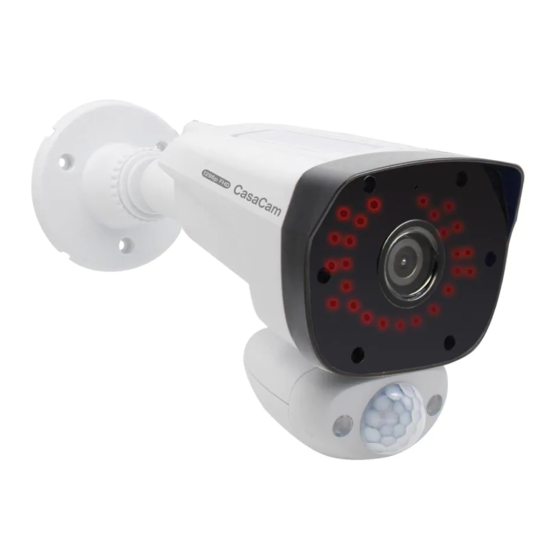
3.2 CAMERA 3.2.1 Night Vision Camera Item What it is What it does Captures the sound on camera side and transmits the sound from Microphone camera to monitor. Catches the video in front of the lens and transmits video from Lens camera to Monitor. -
Page 7: Floodlight Camera
3.2.2 Floodlight Camera Item What it is What it does Captures the sound on camera side and transmits the sound from Microphone camera to monitor. Catches the video in front of the lens and transmits video from Lens camera to Monitor. Indicates the working status of camera. -
Page 8: Set Up The Hardware
4. SET UP THE HARDWARE 4.1 NVR Place the stand on the back of the NVR on a table or install to other flat surfaces, position the antenna. Connect the mouse to the mouse port on the back of the NVR. Connect an AC adaptor to the power input on the back of the NVR. -
Page 9: Set The Antenna Extension
Install the Camera(s) Position the camera where you want it, plug it into power, and check video on the NVR. Move the camera if the view is not what you want. Hold the base of the camera stand where you want to mount it and mark the location of the screw holes. - Page 10 Setup New Password The default user name is “admin”. Please enter your new password and confirm the new password. Select Remember Password, the system will remember the password you have set. After confirm the new password, click Next to enter the next step.
- Page 11 Recording setting type: Continuous, Motion, No Record Left click and drag the table to fill the desired date and time blocks. Under Continuous type, the filled blocks are in GREEN. During the filled date and time blocks, NVR will keep recording continuously. Under Motion type, the filled blocks are in YELLOW.
-
Page 12: Nvr Screen
After finishing upon setting, then click DONE to complete it and enter to live view screen. 5.2 NVR SCREEN The NVR’s screen has 3 main parts: •Live View area. The main screen area displays live video from the camera(s). • Main menu. Those menus allow you to manage the system. •... -
Page 13: Live View Screen
Default: 4 CH split screen. NOTE: System is expandable to 8 CH, go to section 7.1 to set 8 CH view. • Single Channel View. Double click the center of the quadrant to enter Single Channel View mode. Under Signal Channel Mode, double left click the screen to exit then back to Quad Mode. •... -
Page 14: Log In & Password
Number(camera number) Intercom Click here to activate intercom feature to talk back to the camera. Floodlight Control Click here to turn the camera floodlight on/off manually. Zoom Click the area you would like to zoom. Scroll up the mouse to Zoom in, scroll down to zoom out. Color Adjust Click here to adjust Hue, Brightness, Saturation, Contrast, Sharpness. -
Page 15: Main Menu Toolbar
5.2.3 Main Menu Toolbar Move the mouse cursor to the bottom of the screen, below toolbar will display automatically. Click here: Main menu: click here to enter main menu. Click here to lock the toolbar. When you select the lock, you have to enter your Password and click OK to save the setting. -
Page 16: Camera & Display
7.1 Camera & Display Click , to enter the video managing surface. Cameras Select the camera which you want to set. Modify channel name, enable/disable the audio from camera. Display OSD Alpha: set the brightness of screen background. Click+ to turn dark, click- to turn light. ... - Page 17 1. Click the channel you want to pair the camera to, click Pair. 2. Check the status of camera working indicator: Quick flashing: under pairing mode Slow flashing: unpaired or out of range Solid green: paired Please make sure the camera is powered on, then press and hold the pair button ( on the back of the camera) about 5 seconds until the working indicator light turn off, then wait until the working indicator is flashing quickly, means the camera is ready to pair.
-
Page 18: Record
Click to add a camera from another 3 cameras. For example, click on the right of CH1, then select CH4. That means, CH4 will transmit the signal through CH1, finally transmit to NVR. Bring both cameras near the NVR to set up the repeater feature. Click Aplply or OK to save the setting, click Refresh to refresh the connecting datas. -
Page 19: Playback
Select the Channel you want to set. Copy To Select here copy the same setting to all channels. Select the type of recording you’d like to activate Recording setting type: Continuous, Motion, No Record Left click and drag the table to fill the desired date and time blocks. ... - Page 20 Select channel from 1-8, you can select the channel you would like to review. You can also select several channels a time and filter the video out. When filtering the video, system loads up to 4 channels at a time. Select Continuous, filter the videos under continuous recording mode.
-
Page 21: Light Setting
7.4 Light Setting Light setting (only available when the monitor connects to VC2000L floodlight camera) Click , to enter light settings section. Select the Channel you want to set. Duration: click here to set how long the light should be switched on after the movement has been ... -
Page 22: Motion & Alarm
7.5 Motion & Alarm Click , to enter the video detection setting. Select the channel you want to set. Set the sensitivity of the VMD sensor: Highest-High-Medium-Low-Lowest Highest: motions are more easily detected. Lowest: motions are least easily detected. PIR enable: default value is selected. -
Page 23: Hard Drive
After set up the mask area, click the “Return” to save and exit. Audio Alert: select here, audio alert will be heard from NVR once motion is detected. Push notification: select here, you will receive a push notification from your smart phone once ... -
Page 24: Advanced
If above 1, 6 and 11 channel still not working, you may have to try one by one to find the most appropriate channel. 7.8 Advanced Click , to enter advanced setting surface. Maintenance. Auto Reboot: Determine how often an auto reboot will occur. ... -
Page 25: App Remote
Connect the NVR to your router using an Ethernet cable so that it has an Internet connection. 8.2 APP Remote 8.2.1 Add camera Touch the App icon “WNVR Pro” to launch the app. Add the Devise UID of your NVR to App. Go to NVR Main Menu-SYSTEM-Info to find the UID of NVR. -
Page 26: Operating The App
Device name: change the device name to what you want. User name: default user name: admin, the user name is the same as the NVR Password: input the password (the password should be exactly the same as what you have set on NNR). - Page 27 QUAD VIEW→SINGLE VIEW b) Settings to enter this surface. Tap Setting, to turn on/ff the 2G/3G/4G network remind, to view the mobile data traffic statistics or empty data, to select preview mode. Tap Screenshot/Recording to enter the file list, you can ...
-
Page 28: Specifications
8. SPECIFICATIONS Monitor Screen size 10.1” LCD Screen Resolution 1024(H)×600(V) Video input 4x1296p. System expandable to 8 x 1296p. Video Video format H.265 Audio output Built-in speaker Audio Audio format G7.11A Two way audio Recording resolution 720p/960p/1296p Record Recording mode Continuous recording, motion recording Hard Disk Type... - Page 29 Wireless Camera Resolution 300W 2304*1296 Sensor 1/2.7" CMOS sensor Minimum illumination 0.02Lux @(F1.8,AGC ON) , 0 Lux with IR 2.8mm(night vision camera) Lens 3.6mm(floodlight camera) 109 (night vision camera) Viewing Angle (horizontal) 88 (floodlight camera) 120 (night vision camera) Viewing Angle (Diagonal ) 100 (floodlight camera) Camera Day &...
-
Page 30: Trouble Shooting
9. TROUBLE SHOOTING If… Try… Ref. Section… Forget Password Go to NVR to reset the password 5.2.2 Log In & Forget the NVR password. Password Forget the password to access the App. Can’t Connect to the App Make sure NVR is connected to your ... -
Page 31: Fcc Regulations
10. FCC REGULATIONS Part 15 Compliance Statement This device complies with Part 15 of the FCC Rules. Operation is subjected to the following two conditions: (1) this device may not cause harmful interference, and (2) this device must accept any interference received, including interference that may cause undesired operation.
Need help?
Do you have a question about the VS2104 and is the answer not in the manual?
Questions and answers
Will system allow download of app on laptop and iPhone while connected to intranet vs internet?