Table of Contents
Advertisement
Advertisement
Table of Contents

Related Manuals for Alkin W3 Series


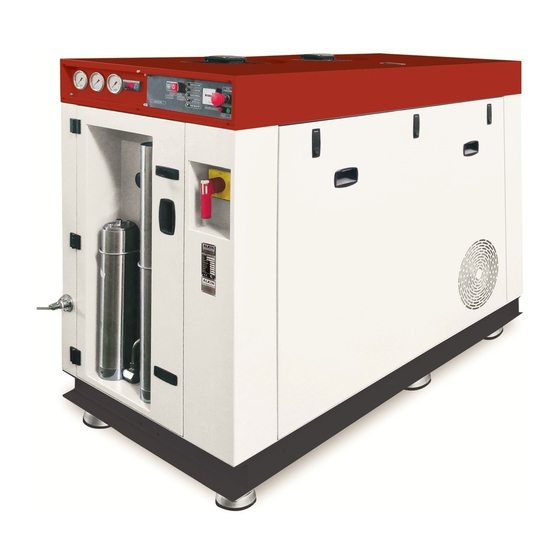
Summary of Contents for Alkin W3 Series
- Page 1 IGH PRESSURE AIR COMPRESSORS ERIES...
- Page 3 P R E S S U R E A I R C O M P R E S S O R HIGH PRESSURE AIR COMPRESSORS (W3 SERIES) Instruction Manual & Parts List I n s t r u c t i o n Manual...
- Page 5 High Pressure Air Compressors This manual or any parts thereof cannot be copied by any means, or used for any other purposes © other than servicing Alkin W3 series compressors, unless specific permission of Alkin ® in writing is received.
-
Page 7: Table Of Contents
1.1.7 Electrical Shock ................8 1.1.8 Lifting ....................8 1.1.9 Labels ....................8 2.0 General information on W3 series 3 Stage compressors ....... 10 2.1 General ..............................10 2.2 Thechnical Specifications ......................11 2.3 P&I (Process & Instrument) Diagram ..................12 2.3 Principles of Operation ........................ -
Page 8: Servicing 3 Rd Stage Valve
5.11 Maintenance procedures ......................30 5.11.1 General ..................30 5.11.3 Servicing 1 stage valve .............. 30 5.11.4 Servicing 2 stage valve ............. 30 5.11.5 Servicing 3 stage valve .............. 31 5.11.6 Piston ring replacement ............... 32 5.11.7 Oil seal replacement ..............33 5.11.8 Piston&piston pin removal and replacement ...... - Page 9 C O M P R E S S O R Foreword Your new ALKIN air compressor will provide you with the solid and reliable performance that you should expect from a heavy-duty industrial air compressor. Please read this manual carefully before you operate your compressor. This will enable you to start-up your compressor in in the maintenance section of this manual.
- Page 10 S E R I E S H I G H P R E S S U R E A I R C O M P R E S S O R ©ALKIN COMPRESSORS...
-
Page 11: Safety
1.1 General 1.1.1 General safety information All ALKIN air and gas compressors are designed and manufactured with equipment & components that allow safe operation of the compressors. It is the user’s responsibility however; to safely operate and maintain the compressor, observe the rules and instructions, as well as the local safety codes, to minimize the risk of accidents and injury. -
Page 12: Moving Parts
Operate the compressor only in well ventilated areas. Lubricants used in this compressor are typical industrial oils designed for use in high-pressure compressors. Accidental ingestion and skin contact should be avoided. Wash with soap and water after skin contact. If swallowed, seek medical treatment promptly. ©ALKIN COMPRESSORS... -
Page 13: Electrical Shock
Lift the compressor no higher than necessary. Keeps lift operator in constant attendance whenever the compressor suspended. Set the compressor down on level surfaces, capable of carrying its full weight. 1.1.9 Labels Symbol Meaning MOVING EQUIPMENT SELF STARTING HOT SURFACE ELECTRIC GROUND ELECTRICAL HAZARD ©ALKIN COMPRESSORS... - Page 14 S E R I E S H I G H P R E S S U R E A I R C O M P R E S S O R ©ALKIN COMPRESSORS...
-
Page 15: General Information On W3 Series 3 Stage Compressors
70 Bars (1015 psi) to 250 Bars (3625 psi). Do not attempt to modify a compressor to operate at a higher-pressure range without written approval of Alkin. Failure to do so may result in heavy damage to equipment, injury or death. -
Page 16: Thechnical Specifications
C O M P R E S S O R The W3 series compressors are equipped with radiator between the 1st & 2nd stage cylinders and finned tube intercooler between the 2nd and 3rd stage cylinders and stainless steel aftercooler downstream the 3rd stage cylinder. A moisture trap (or condensate separator) is installed downstream the 2nd stage intercooler and downstream the aftercooler. -
Page 17: P&I (Process & Instrument) Diagram
180 bars (2610 psi), a pressure level where the purification process is more efficient than at lower pressures. The air is than ready to be directed to a filling panel and with proper connections to the cylinders to be filled. ©ALKIN COMPRESSORS... -
Page 18: Description Of Major Components
Head Assembly: The head assemblies are the cover plates and the valve assemblies housed inside; these assemblies are mounted on top of the cylinders. The valve assemblies inside the covers need to be maintained periodically; they need to ©ALKIN COMPRESSORS... -
Page 19: Major Components - System
Therefore the force on the top is larger and causes the piston to sit and seal the high-pressure vent port. The drain valves are controlled by a solenoid mounted on the pilot valve fitting. It receives compressed air from the 2 stage ©ALKIN COMPRESSORS... - Page 20 Electric Motor W3 Series of compressors can be driven by electric motor. They are belt-driven. They have an hourmeter which shows the working hours of the unit on the control panel on W3 Canopy models.
- Page 21 If the LED is lit, it means the compressor has reached to the set upper pressure value and in stand- by condition. General Failure LED If the LED is lit, one of the following failures may have occurred; ©ALKIN COMPRESSORS...
-
Page 22: Description Of Controls
This control system is standard on all single pressure compressors. Drain Control: W3 Series compressors can be automatically drained by automatic drain valves. These drain valves are controlled by 3 way Solenoid Valve which is normally closed. This solenoid valve supplies or cuts the control air on the drain valves, thus letting them to open or close. -
Page 23: Installation
Discharge Piping: If piping is required between the compressor package and the filling station, properly selected stainless stell pipes must be used. The piping should be installed in full compliance with all Federal, State and local codes, standards and regulations. If required, consult the manufacturer for details. ©ALKIN COMPRESSORS... -
Page 24: Electrical Check
Stop the unit before it gets too warm. Connect the lines to the valve heads which are previously disconnected. Close all the valves and put a cap onto the intake port against the dust and fumes may enter. ©ALKIN COMPRESSORS... - Page 25 Load new oil and check the oil level. Run the compressor till it gets warm while the filling valves and all the drain valves are open. Make sure that there is no leakage. You can run the compressor after completing all the steps mentionned above. ©ALKIN COMPRESSORS...
- Page 26 S E R I E S H I G H P R E S S U R E A I R C O M P R E S S O R ©ALKIN COMPRESSORS...
-
Page 27: Operation
FILL IN THE comissioning report and return a copy to the manufacturer for track record. 4.2 Oil recommendation The oil level should be checked daily. Top up to the overfill point when required. On all W3 Series Compressors use the following oil only: Type Quantity... -
Page 28: Adjustment
Compressor will stop when it reaches the adjusted upper pressure. Standard Pressure Switches used on Alkin Automatic Start/Stop controlled W3 units have standard differential of 20 Bar. In other words, lower pressure is set automatically at 20 Bar below the set working pressure. Compressor will restart when the final pressure decreases to a pressure 20 Bar below the set working pressure. - Page 29 If safety valve leaking, replace it. Fill in the following forms (total 2 pages) at the initial start up. Send a copy to the manufacturer for record keeping, and retain the original report n the file of your compressor. ©ALKIN COMPRESSORS...
- Page 30 S E R I E S H I G H P R E S S U R E A I R C O M P R E S S O R ©ALKIN COMPRESSORS...
- Page 31 Bolitng down-canopy/sub-base Piping in the compressor intact Oil Type Oil Level in the crankcase External Conn.s & Pipework Suitable All electrical connections checked Mains Supply Voltage and Freq. Other Remarks ©ALKIN COMPRESSORS...
- Page 32 50 Bar 100 Bar 150 Bar Engineer in charge of the plant Full Name Remarks Singature Date Distributor / Manufacturer’s Representative Attending the Commissioning Full Name Remarks Signature Date Other Attendants Full Name Remarks Singature Date ©ALKIN COMPRESSORS...
-
Page 33: Maintenance
If a bank system exists, isolate by closing the appropriate valves. CAUTION! Ambient temperature where the compressor is located must be between + 5◦ C and + 45◦ C. ©ALKIN COMPRESSORS... -
Page 34: Maintenance Parts Control Table
Oil seal Note: Check the oil seal every 1000 operating hours and replace them if needed Annually Purifier Note: Have the purifier on your unit pressure tested to the authorized body according to the pressurized equipment test regulations. ©ALKIN COMPRESSORS... -
Page 35: Maintenance Parts Replacement Table
(see Maintenance Table). 5.11.4 Servicing 2 stage valve 2nd stage valves are concentric ring type and are similar in construction. To inspect and clean the 2nd stage valve, observe the following step-by-step procedure: ©ALKIN COMPRESSORS... - Page 36 Use new o-rings and gaskets. When reassembling the valve, make sure all parts are replaced exactly as removed and that new gaskets and “O” rings are used. It is important to install original Alkin “O” rings as these are made of special high temperature resistant material and ordinary o-rings will be promptly damaged causing failures ©ALKIN COMPRESSORS...
-
Page 37: Piston Ring Replacement
Caution! Do not attempt to deglaze the cylinder bore with a harsh abrasive agent. The use of such abrasive agents usually results in oil carryover and faulty compressor. ©ALKIN COMPRESSORS... -
Page 38: Oil Seal Replacement
-with the piston inside- off the crankcase. The piston can now be pushed out of the cylinder. To remove the piston from the connecting rod, follow the procedure outlined under “Piston Pin Removal and Replacement” on this page. To Replace Piston and Cylinders –Proceed as follows: ©ALKIN COMPRESSORS... -
Page 39: Air Head Replacement
200 hours. If necessary, clean the housing as well. Use a clean lint free cloth to clean. Make sure not to leave any parts or rugs inside the housing, which may block the air passages in the caps. Purifier: ©ALKIN COMPRESSORS... - Page 40 Put the two bolts (2) in place to turn the cover (5) same bolts (2). Tighten the cover until it is flat with by hand. Turn the cover (5) and remove the whole the purifier chamber top surface. assembly from the purifier chamber. ©ALKIN COMPRESSORS...
- Page 41 Remove the tool (1) and the adapter (3); the installation of the cartridge is completed. For filters, use similar procedures, except for the cartridge which is not refillable and it needs to be replaced periodically. See the instruction manual for details. ©ALKIN COMPRESSORS...
- Page 42 H I G H P R E S S U R E B R E A T H I N G A I R C O M P R E S S O R ©ALKIN Kompresör Sanayi ve Ticaret Limited Şirketi...
-
Page 43: Trouble Shooting
Wrist pins and journals are worn Replace complete pin and rod assembly. 6.4 MILKY OIL IN RECERVOIR High moisture content in the ambient Pipe air intake from less humid source. Change oil more frequently. ©ALKIN Kompresör Sanayi ve Ticaret Limited Şirketi... - Page 44 Excessive leaks in the plant piping Relieve the tank and piping air pressure; repair leaks. Warning! Do not service tank, valves, piping etc. With air/gas in the system. Relieve alla ir before attemting any repairs. ©ALKIN Kompresör Sanayi ve Ticaret Limited Şirketi...
- Page 45 6.17 COMPRESSOR DOESN’T UNLOAD WHEN STOPPED Solenoid Valve faulty Check the Solenoid Valve Automatic drain valves blocked Check, disassemble and clean the drain valves; install new o-ring and seat if necessary ©ALKIN Kompresör Sanayi ve Ticaret Limited Şirketi...
- Page 46 Carbonization on valves Clean; make sure that the ambient temperatures are within permissible limits. Check oil filter, rings and drain purifier. Replace cartridge if necessary. ©ALKIN Kompresör Sanayi ve Ticaret Limited Şirketi...
-
Page 47: Parts List
H I G H P R E S S U R E B R E A T H I N G A I R C O M P R E S S O R 7.0 Parts list P a r t s L i s t ©ALKIN Kompresör Sanayi ve Ticaret Limited Şirketi... -
Page 48: Crankcase Assy
H I G H P R E S S U R E B R E A T H I N G A I R C O M P R E S S O R 4.1 Crankcase Assy ©ALKIN Kompresör Sanayi ve Ticaret Limited Şirketi... - Page 49 BONDED SEAL - 1/2" 1.36 AYD-62 HEX. CAP - 1/2" 1.37 AYD-359 O-RING -Ø247x3 1.38 3004-21 CRANKCASE COVER 1.39 6882-09 BOLT - M8x20 1.40 6821-05 BONDED SEAL - 3/4" 1.41 AYD-86 PLUG - 3/4" ©ALKIN Kompresör Sanayi ve Ticaret Limited Şirketi...
-
Page 50: Connecting Rods
H I G H P R E S S U R E B R E A T H I N G A I R C O M P R E S S O R 4.2 Connecting Rods ©ALKIN Kompresör Sanayi ve Ticaret Limited Şirketi... - Page 51 SHIM – Ø34 2.13 3019-51 BEARING - INA RNA 6902 2.14 3005-91 ARTICULATED ROD 2.15 3022-30 BEARING - NK 28/30 INA 2.16 3000-84 SHIM 2.17 AYD-357 BEARING - NK 30/30 İNA 2.18 0023-18.01 ARTICULATED ROD ©ALKIN Kompresör Sanayi ve Ticaret Limited Şirketi...
-
Page 52: 1St Stage Assy
H I G H P R E S S U R E B R E A T H I N G A I R C O M P R E S S O R 4.3 1st Stage Assy ©ALKIN Kompresör Sanayi ve Ticaret Limited Şirketi... - Page 53 3.15 3000-41 GASKET 3.16 7868-10 BOLT - M10x100 3.17 7091-12 WASHER - M10 3.18 3024-32 TUBE – Ø10 3.19 7672-19 ELBOW - 1/4"xØ10 3.20 7192-02 COUPLING - 1/4" 3.21 7070-08 NIPPLE - 1/4"x1/4” ©ALKIN Kompresör Sanayi ve Ticaret Limited Şirketi...
-
Page 54: 2Nd Stage Assy
H I G H P R E S S U R E B R E A T H I N G A I R C O M P R E S S O R 4.4 2nd Stage Assy ©ALKIN Kompresör Sanayi ve Ticaret Limited Şirketi... - Page 55 BODY - CAGE VALVE 4.23 0441-03 O-RING - Ø53,57x3,53 4.24 0440-01 COVER - CAGE VALVE 4.25 7867-34 SETSCREW - M16x50 4.26 7867-35 SETSCREW - M16x60 4.27 7091-44 WASHER - M16x2mm 4.28 7228-00 CAP NUT - M16 ©ALKIN Kompresör Sanayi ve Ticaret Limited Şirketi...
-
Page 56: 3Rd Stage Assy
H I G H P R E S S U R E B R E A T H I N G A I R C O M P R E S S O R 4.5 3rd Stage Assy ©ALKIN Kompresör Sanayi ve Ticaret Limited Şirketi... - Page 57 DISK – INTAKE 6202-01 SPRING – INTAKE 6202-02 RETAINER 6486-03 RETAINING RING 6800-05 5.20 6800-03 COPPER WASHER 5.21 6486-04 O-RING -Ø40x5 5.22 7065-03.02 VALVE CAP 5.23 3022-44 BOLT – M12x80 ©ALKIN Kompresör Sanayi ve Ticaret Limited Şirketi...
-
Page 58: Pipe Lines - 1St Stage
H I G H P R E S S U R E B R E A T H I N G A I R C O M P R E S S O R 4.6 Pipe Lines – 1st Stage ©ALKIN Kompresör Sanayi ve Ticaret Limited Şirketi... - Page 59 TUBE – Ø20 6.32 3004-48 ELBOW - 1”xØ20 6.33 7078-41 NIPPLE - 1/4"BSPx1/4”NPT 6.34 7866-20 MANIFOLD 6.35 7933-90 SAFETY VALVE - 9 BAR 6.36 7084-21 ELBOW - 1/4"NPTx1/4"BSP 6.37 7083-02 PLUG - 1/4" ©ALKIN Kompresör Sanayi ve Ticaret Limited Şirketi...
-
Page 60: Pipe Lines - 2Nd Stage
H I G H P R E S S U R E B R E A T H I N G A I R C O M P R E S S O R 4.7 Pipe Lines – 2nd Stage ©ALKIN Kompresör Sanayi ve Ticaret Limited Şirketi... - Page 61 NUT - M4 7.37 7084-03 ELBOW – 1/4" 7.38 7078-41 NIPPLE - 1/4"BSP x 1/4”NPT 7.39 3024-30 REGULATOR – 1/4" 7.40 7078-02 NIPPLE - 1/8” 7.41 7185-03 REDUCTION - 1/4"x1/8” 7.42 7192-02 COUPLING - 1/4" ©ALKIN Kompresör Sanayi ve Ticaret Limited Şirketi...
-
Page 62: Pipe Lines - 3Rd Stage
H I G H P R E S S U R E B R E A T H I N G A I R C O M P R E S S O R 4.8 Pipe Lines – 3rd Stage ©ALKIN Kompresör Sanayi ve Ticaret Limited Şirketi... - Page 63 SAFETY VALVE - 265 BAR 8.16 7185-03 REDUCTION - 1/4"x1/8” 8.17 6753-08 SOCKET 8.18 90501-21 TEMPERATURE TRANSMITTER 8.19 2000-27 TUBE – Ø10 8.20 7145-02 NUT - 5/8” (8 MM) 8.21 3007-43 ELBOW - 3/8”xØ10 ©ALKIN Kompresör Sanayi ve Ticaret Limited Şirketi...
-
Page 64: Intercooler
H I G H P R E S S U R E B R E A T H I N G A I R C O M P R E S S O R 4.9 Intercooler ©ALKIN Kompresör Sanayi ve Ticaret Limited Şirketi... - Page 65 O-RING –Ø32x3 9.05 3020-92 MANIFOLD 9.06 3021-15 PLUG 9.07 6882-13 BOLT - M6x45 9.08 3023-53 RETAINING PLATE 9.09 7091-33 WASHER - M10 9.10 7091-35 SPRING WASHER - M10 9.11 7867-91 BOLT - M10x25 ©ALKIN Kompresör Sanayi ve Ticaret Limited Şirketi...
-
Page 66: Aftercooler
H I G H P R E S S U R E B R E A T H I N G A I R C O M P R E S S O R 4.10 Aftercooler ©ALKIN Kompresör Sanayi ve Ticaret Limited Şirketi... - Page 67 BRACKET 10.06 7291-06 BOLT - M6x35 10.07 7867-37 FITTING - 1/4"xØ10 10.08 7425-01 COUPLING – 1/4" 10.09 7192-30 TUBE 10.10 2000-22.02 CLAMP 10.11 7291-50.01 BRACKET 10.12 7291-06.01 ©ALKIN Kompresör Sanayi ve Ticaret Limited Şirketi...
-
Page 68: Out Line
H I G H P R E S S U R E B R E A T H I N G A I R C O M P R E S S O R 4.11 Out Line ©ALKIN Kompresör Sanayi ve Ticaret Limited Şirketi... - Page 69 11.29 7084-09 ELBOW - 1/4" 11.30 7078-41 NIPPLE - 1/4"BSPx1/4”NPT 11.31 80071-00 PRESSURE SWITCH - XML-A300D2S11 11.32 3007-76 COUPLING - ÇIKIŞ 3/8” 11.33 6884-21 NUT - M6 FIBERED 11.34 7867-09 BOLT - M6x20 ©ALKIN Kompresör Sanayi ve Ticaret Limited Şirketi...
-
Page 70: Filter Ve Purifier
H I G H P R E S S U R E B R E A T H I N G A I R C O M P R E S S O R 4.12 Filter ve Purifier FILTER PURIFIER ©ALKIN Kompresör Sanayi ve Ticaret Limited Şirketi... - Page 71 BODY 7168-19 BOLT - M6x10 7867-67 WASHER - M6 7091-17 RING 7168-28 BOTTOM CAP - 3/8” 7168-81 17.00 7673-00 CARTRIDGE 18.00 7047-13 O-RING -Ø12,37x2,62 19.00 7047-14 O-RING -Ø9,92x2,62 ©ALKIN Kompresör Sanayi ve Ticaret Limited Şirketi...
-
Page 72: Discharge Line
H I G H P R E S S U R E B R E A T H I N G A I R C O M P R E S S O R 4.13 Discharge Line ©ALKIN Kompresör Sanayi ve Ticaret Limited Şirketi... - Page 73 TUBE – Ø6 20.24 2000-32 TUBE – Ø6 20.25 7187-32 ELBOW - 1/2"xØ16 20.26 3024-34 HOSE – Ø16 20.27 3024-35 HOSE – Ø16 20.28 7187-33 FITTING - 1/2"xØ16 20.29 7672-17 ELBOW - 1/4"xØ6 ©ALKIN Kompresör Sanayi ve Ticaret Limited Şirketi...
-
Page 74: Pressure Gauge Lines
H I G H P R E S S U R E B R E A T H I N G A I R C O M P R E S S O R 4.14 Pressure Gauge Lines ©ALKIN Kompresör Sanayi ve Ticaret Limited Şirketi... - Page 75 TUBE – Ø6 21.08 3024-40 TUBE – Ø6 21.09 3024-41 TUBE – Ø6 21.10 7820-00 NIPPLE 21.11 7235-03 PRESSURE GAUGE – 25BAR 21.12 7235-05 PRESSURE GAUGE – 100BAR 21.13 7235-07 PRESSURE GAUGE – 400BAR ©ALKIN Kompresör Sanayi ve Ticaret Limited Şirketi...
-
Page 76: General Connectors
H I G H P R E S S U R E B R E A T H I N G A I R C O M P R E S S O R 4.15 General Connectors ©ALKIN Kompresör Sanayi ve Ticaret Limited Şirketi... - Page 77 DOOR SWITCH 22.33 7868-15 BOLT - M4x35 22.34 6885-06 WASHER - M4 22.35 6884-25 NUT - M4 FIBERED 22.36 7867-60 BOLT - M6x30 22.37 7091-17 WASHER - M6 22.38 6884-21 NUT - M6 FIBERED ©ALKIN Kompresör Sanayi ve Ticaret Limited Şirketi...
- Page 78 H I G H P R E S S U R E B R E A T H I N G A I R C O M P R E S S O R ©ALKIN Kompresör Sanayi ve Ticaret Limited Şirketi...
-
Page 79: Drawings
H I G H P R E S S U R E B R E A T H I N G A I R C O M P R E S S O R 8.0 Drawings Drawings ©ALKIN Kompresör Sanayi ve Ticaret Limited Şirketi... - Page 80 H I G H P R E S S U R E B R E A T H I N G A I R C O M P R E S S O R ©ALKIN Kompresör Sanayi ve Ticaret Limited Şirketi...
- Page 81 H I G H P R E S S U R E B R E A T H I N G A I R C O M P R E S S O R Electrical Drawings ©ALKIN Kompresör Sanayi ve Ticaret Limited Şirketi...
- Page 82 H I G H P R E S S U R E B R E A T H I N G A I R C O M P R E S S O R ©ALKIN Kompresör Sanayi ve Ticaret Limited Şirketi...
- Page 83 H I G H P R E S S U R E B R E A T H I N G A I R C O M P R E S S O R ALKIN KOMPRESÖR SAN. Ve Tic. Ltd. Şti İbrahim Turan Caddesi No 127...
Need help?
Do you have a question about the W3 Series and is the answer not in the manual?
Questions and answers