
Related Manuals for TESTO 550s


Summary of Contents for TESTO 550s
- Page 1 550s / testo 557s digital manifold Instruction manual 1.800.561.8187 information@itm.com www. .com...
-
Page 2: Table Of Contents
Product-specific approvals ..............7 Product-specific information............... 8 Use ......................8 Product description ................9 Overview of the testo 550s ................. 9 Overview of the testo 557s ................10 Overview of main menu ..................11 Control keys ..................... 12 First steps ................... 12 Inserting (rechargeable) batteries .............. - Page 3 Contents Duration ........................38 8.4.1 Brightness ....................... 38 8.4.2 8.4.3 Auto Off ........................39 Auto Tfac (Temperature compensation factor) ............40 8.4.4 Units ........................41 8.4.5 8.4.6 Language ........................ 42 Setup Wizard ......................43 8.4.7 Factory Settings ...................... 44 8.4.8 8.4.9 Instrument .......................
- Page 4 Contents testo DataControl archiving software ..............66 System requirements ....................66 9.9.1 9.9.1.1 Operating system ........................66 PC ............................66 9.9.1.2 Procedure ........................ 67 9.9.2 Maintenance..................68 10.1 Calibration ......................68 Cleaning the instrument ..................68 10.2 Keeping connections clean ................69 10.3...
-
Page 5: About This Document
Control keys of the instrument or buttons of the program interface. 2 Safety and disposal Please observe the Testo information document (enclosed with the product). 3 Product-specific approvals Please find the current country approvals in the Approvals and Certifications document. -
Page 6: Product-Specific Information
They may only be used by qualified authorized personnel. The functions of the instruments testo 550s and testo 557s mean they can replace mechanical manifolds, thermometers and pressure/temperature charts. Pressures and temperatures can be applied, adapted, tested and monitored. -
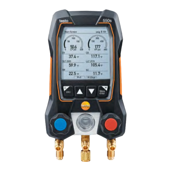
Page 7: Product Description
6 Product description 6 Product description Overview of the testo 550s Mini-DIN probe socket for NTC Foldable suspension device temperature probe, with socket (rear). cover Rear Battery compartment • Mini USB port for firmware • update 3 Display. Instrument status icons... -
Page 8: Overview Of The Testo 557S
6 Product description Overview of the testo 557s Mini-DIN probe socket for NTC Foldable suspension device temperature probe, with socket (rear). cover Rear Battery compartment • • Mini USB port for firmware update 3 Display. Instrument status icons It is not possible to charge rechargeable batteries in the instrument. -
Page 9: Overview Of Main Menu
Overview of main menu Refrigeration Evacuation Pressure Leak Test Measuring mode Target Superheat Compressor Test (DLT) Delta T Bluetooth ® Connection to the testo Smart App or Smart Probes Settings Duration Brightness Auto Off Auto Tfac (Temperature compensation factor) Units Language Setup Wizard... -
Page 10: Control Keys
7 First steps Control keys Symbol Meaning • Open menu Confirm input • Switch on the display illumination: • Press and hold the key for >2s • Switch off the display illumination: Press and hold the key for >2s Change/navigate the display screen. Switches to the measurement view •... -
Page 11: Switching The Instrument On And Off
Settings menu. Setup wizard When the testo 550s / testo 557s is started up for the first time and after the factory settings have been reset, the setup wizard is activated and guides you step-by-step through the following setup parameters. -
Page 12: Using The Product
8 Using the product Take a photo of the QR code with a mobile device of the testo Smart App and press [Menu/Enter] to confirm. The measurement menu is displayed. 8 Using the product Preparing for measurement Operating the valve positioners 8.1.1... -
Page 13: Automatic Mode
8 Using the product Automatic mode 8.1.2 The manifold automatically detects the pressure difference between the low- pressure and high-pressure sides. If the measured pressure on the low pressure side is 14.7 psi higher than on the high pressure side, a dialogue appears and the display can be changed accordingly. - Page 14 8 Using the product These can be fixed cable temperature probes or testo Smart Probes (e.g. testo 115i). Before each measurement, check that the refrigerant hoses are in perfect condition. Before each measurement, zero the pressure sensors. All connections [▲] (P=O) must be pressureless (ambient pressure).
- Page 15 Connect the refrigerant hoses for low-pressure side (blue) and high- pressure side (red) to the measuring instrument. Connect the refrigerant hoses to the system. Connect testo 115i or fixed cable probes. Set refrigerant. Press the key [▼] (Rxx) (refrigerant number according to ISO 817).
- Page 16 These then appear at the beginning of the refrigerant list. To do this, the testo Smart App must be connected to the instrument via Bluetooth. In the refrigerant list (App), now choose the refrigerant as a favorite by clicking on the star.
-
Page 17: Evacuation
The testo 552i is recommended for carrying out the measurement. The measurement is also possible without the testo 552i, with testo 550s/testo 557s. However, this is not advisable due to insufficient accuracy. - Page 18 8 Using the product Measuring Mode menu is displayed. Press [▲] / [▼] to select Evacuation and press [Menu/Enter] confirm. Configure Target Lines menu is displayed. Evacuation Target will be set at 500 microns as a default. Maximum decay target will be set at 1000 microns as a default. Adjust the Target Line value...
- Page 19 Confirm the entries in steps 4 and 5: Press [▼] to select and press [Menu/Enter] to confirm. A connection is established with available Bluetooth ® probes. testo 552i is switched on and connected automatically. Evacuation measurement menu is displayed. 1.800.561.8187 information@itm.com www. .com...
-
Page 20: Pressure Leak Test
Surface temperature probes (e.g. testo 115i) can also be used for the temperature-compensated leak testing, but must not be used to measure surface temperature. They must be positioned as far as possible to measure the air temperature. - Page 21 8 Using the product The testo 550s or testo 557s manifold is used to carry out the measurement. The instrument is switched on and the measurement menu is displayed. Hoses are connected. Press [Menu/Enter]. Press [▲] / [▼]...
- Page 22 8 Using the product testo 905i / testo 605i is switched on and automatically connected. Other temperature probes compatible with testo 550s / testo 557s can be connected. Pressure Leak Test menu is displayed. T Comp is shown on the display if a compatible probe is connected via Bluetooth ®...
-
Page 23: Target Superheat
Target Superheat 8.2.4 This feature makes it possible to connect the testo 550s and testo 557s manifolds to two additional testo 605i Smart Probes in order to calculate the target superheat. This application can only be used for split air conditioning systems/heat pumps with a fixed expansion valve. - Page 24 The values can either be configured manually via Manual Input recorded by the testo 605i via Smart Probe. When a Smart Probe selected, available testo 650i instruments are displayed for the connection. Adjust values for Outdoor Dry Bulb Temp. [▲] Outdoor Dry Bulb Temp.
- Page 25 8 Using the product Adjust the Return Air Wet Bulb Temp. value Press the [▲] / [▼] key and in the Return Air Wet Bulb Temp. field, select Manual Input. [Menu/Enter] Press to confirm. The field is activated. Press [▲] / [▼] to set the value.
- Page 26 Connect the refrigerant hoses for low-pressure side (blue) and high- pressure side (red) to the measuring instrument. Connect the refrigerant hoses to the system. Connect testo 115i/fixed cable probes. Set refrigerant. Press the key [▼] (Rxx) (refrigerant number according to ISO 817).
-
Page 27: Compressor Test (Dlt)
Bluetooth. The testo 115i (clamp thermometer) or fixed cable probes are used to carry out the measurement. Before each measurement, check that the refrigerant hoses are in perfect condition. - Page 28 8 Using the product Press [Menu/Enter]. Press [▲] / [▼] to select Measuring Mode and press [Menu/Enter] confirm. Measuring Mode menu is displayed. Press [▲] / [▼] to select Compressor Test (DLT) and press [Menu/Enter] to confirm. The measurement menu is displayed.
- Page 29 8 Using the product Connect the testo 115i or fixed cable probes and third temperature probe to the compressor outlet. Recommended to use a wireless probe for the compressor outline line to not impede the fan blade. Set refrigerant. Press the key [▼] (Rxx) (refrigerant number according to ISO 817).
-
Page 30: Delta T
Temperature 1 and temperature 2 are measured. The difference is shown on the display as the delta temperature. The testo 115i (clamp thermometer) or fixed cable probes are used to carry out the measurement. The instrument is switched on and the measurement menu is ... -
Page 31: Bluetooth
550s / testo 557s have the option of establishing a Bluetooth ® connection with wireless probes as well as a connection to the testo Smart App at the same time. If the testo 550s or testo 557s is used with Smart Probes, they must be at least 8 in apart. -
Page 32: Establishing A Connection
Bluetooth 4.0. ® Once the connection between the app and the testo 550s and testo 557s has been successfully established, the app is in second screen mode. This is indicated by a yellow frame in the app. This means that all measurement data from the manifold is being mirrored on the app. -
Page 33: Switching On/Off
8 Using the product Switching on/off 8.3.3 The instrument is switched on and the measurement menu is displayed. Press [Menu/Enter]. [▲] / [▼] to select Bluetooth: Press [Menu/Enter] and press to confirm. Bluetooth menu is displayed. Switching on 8.3.3.1 ... -
Page 34: Switching Off
8 Using the product After opening the App, the instrument is automatically connected if it is within range. The instrument does not have to be connected to the smartphone/tablet via settings beforehand. Switching off 8.3.3.2 The Bluetooth menu is activated. ®... -
Page 35: Settings
8 Using the product Press [▼] to click on the [Completed] button and press [Menu/Enter] to confirm. Bluetooth In the ® menu, you will obtain further information. Display Explanation There is no Bluetooth ® connection, or a flashes potential connection is being searched for. There is a Bluetooth ®... -
Page 36: Duration
8 Using the product Backlight Duration 8.4.1 Set the backlight duration for the display. Settings menu is activated. Press [▲] / [▼] to select Backlight duration and press [Menu/Enter] confirm. Menu properties are displayed. [▲] / [▼] Press to select the backlight duration and press [Menu/Enter] to confirm. -
Page 37: Auto Off
8 Using the product Press [▲] / [▼] to select the Backlight brightness and press [Menu/Enter] to confirm. Menu properties are displayed. Press [▲] / [▼] to select the brightness value (25%, 50%, 75%, 100%) and press [Menu/Enter] confirm. Press [ESC]: 1x main menu view, 2 x measurement menu view. Auto Off 8.4.3 You can manage the energy consumption for your instrument yourself. -
Page 38: Auto Tfac (Temperature Compensation Factor)
8 Using the product Press [▲] / [▼] to select Auto OFF On: The instrument automatically switches off after 30 minutes of inactivity. The instrument switches off automatically if no pressure is measured and no key has been pressed within 10 minutes. As long as pressure is present, the instrument remains on. -
Page 39: Units
8 Using the product Press [▲] / [▼] activate (On)/deactivate (Off) Auto Tfac press [Menu/Enter] to confirm. Press [▲] / [▼] to select the question mark icon and press [Menu/Enter] to open. You will obtain further information on temperature compensation. Press [ESC]: 1x main menu view, 2 x measurement menu view Units 8.4.5... -
Page 40: Language
8 Using the product Adjustable units Measurement Unit Description parameter Temperature °C, °F Set unit for temperature. psi, kPa, MPa, Pressure Set unit for pressure. Prel, Pabs Depending on the chosen unit for pressure: Pressure mode Change between absolute and relative pressure displays. -
Page 41: Setup Wizard
8 Using the product Select language: [▲] / [▼] press [Menu/Enter] to confirm. Selecting the language activates the appropriate presetting of the units of measurement. Press [ESC]: 1 x Units menu, 2 x main menu view, 3 x measurement menu view. Setup Wizard 8.4.7 Settings... -
Page 42: Factory Settings
8 Using the product Barcode is displayed and the testo Smart App can be downloaded from the respective app store. Factory Settings 8.4.8 The instrument is reset to the factory settings. Settings menu is activated. Press [▲] / [▼]... -
Page 43: Instrument
8 Using the product - [Restore Factory Reset] is carried out. Setup Wizard. Instrument 8.4.9 Settings menu is activated. Press [▲] / [▼] to select [Device Info] and press [Menu/Enter] confirm. Versions Info menu is displayed. The following information can be viewed: Serial number •... -
Page 44: Smart App
9 Smart App 9 Smart App App – user interface Open main menu Display of the measurement period Display of calculated measurement results Reading for each probe Can be controlled with different function keys Device status bar Configuration Edit reading display Further symbols on the user interface (without numbering) One level back Exit view... -
Page 45: Main Menu
9 Smart App Search Favorite Delete Further information Display report Multiple selection Main menu Main menu can be accessed via the icon at top left. To exit the main menu, select a menu or right-click on the guided menus. The last screen displayed is shown. -
Page 46: Measurement Menu
9 Smart App Measurement menu The testo Smart App has permanently installed measurement programs. These enable the user to carry out convenient configuration and implementation of specific measuring tasks. The testo Smart App offers the following Measurement menus: Basic view Volume flow –... -
Page 47: Basic View
All Bluetooth ® probes compatible with the testo Smart App are displayed in the Basic view. In all application menus, apart from the volume flow measurement, there are three different screens for the measurement - Live (or also Basic view), Graphic and Table. -
Page 48: Refrigeration
• • Condensation pressure: Subcooling Δtcu/SC The testo 115i clamp thermometer is used for the measurement. An NTC temperature sensor (accessory) must be connected for measuring the pipe temperature and for automatic calculation of superheating and subcooling. Testo Smart Probes (e.g. testo 115i) can be used. - Page 49 9 Smart App Before each measurement, check that the refrigerant hoses are in flawless condition. Before each measurement, zero the pressure sensors. All connections must be pressureless (ambient pressure). Press the button [▲] (P=O) for 2 seconds to zero the sensors. Click on Measure.
- Page 50 9 Smart App Set refrigerant. You have the option of setting up favourite refrigerants in the App. These then appear at the beginning of the refrigerant list. To do this, click on the asterisk next to the refrigerant in the refrigerant list (App).
-
Page 51: Target Superheat
9.3.3 This feature allows the calculation of target superheat in conjunction with the App and additional testo 605i Smart Probes. This application can only be used for split air conditioning systems/heat pumps with a fixed expansion valve. The two connected testo 605i Smart Probes determine the ODDB and RAWB values. - Page 52 9 Smart App Make the required settings. Click on Apply Configuration. Set refrigerant. The newly set refrigerant is displayed in the refrigerant list. 1.800.561.8187 information@itm.com www. .com...
-
Page 53: Pressure Leak Test
They must be positioned as far as possible to measure the air temperature. The 550i, 550s or 557s manifold is used to perform the measurement. Click on Measure. Click on Leakage test. - Page 54 9 Smart App Make the required settings. Click on Apply Configuration. Click on Start. The measurement starts. Values currently being measured are displayed. Measured values are saved. The values can be exported or a report can be created. 1.800.561.8187 information@itm.com www.
-
Page 55: Evacuation
9 Smart App Evacuation 9.3.5 With the Evacuation application, foreign gases and moisture can be removed from the refrigeration circuit. Click on Measure. Click on Evacuation. The Evacuation measurement menu opens. Click on Configuration menu opens. Make the required settings. Click on Apply Configuration. -
Page 56: Customer
9 Smart App Click on Start. The measurement starts. Values currently being measured are displayed. Measured values can be saved or a new measurement can be started. Customer Customer In the menu, all customer and measuring site information can be created, edited and deleted. -
Page 57: Creating And Editing Measuring Sites
9 Smart App + New customer. Click on A new customer can be created. Store all relevant customer data. Click on Save. The new customer was saved. Creating and editing measuring sites 9.4.2 Click on Main menu opens Click on Customer. - Page 58 9 Smart App + New measuring site. Click on A new measuring site can be created. Store all relevant measuring site information. Click on right tab Parameters. Select further parameters. For the duct, outlet or duct with k-factor measuring sites, further parameter settings can be implemented.
-
Page 59: Memory
9 Smart App Memory Memory In the menu, you can call up all the measurements stored on the mobile device, analyze them in detail and also create and save csv data and PDF reports. When clicking on a measurement, an overview of the measurement results is displayed. -
Page 60: Sensors
9 Smart App Sensors All sensors used with the App can be found in the Sensors menu. There, you can view general information about currently connected probes as well as recently connected probes. Information 9.6.1 Information is stored for each probe. The App is connected to an instrument. -
Page 61: Settings
9 Smart App Settings 9.6.2 Settings can also be made for each probe. The probe is connected to the App. Click on Main menu opens. Click on Sensors. The Sensors menu opens. Click on one of the displayed probes. Click on the Settings tab. -
Page 62: Measurement Settings
9 Smart App Measurement settings 9.7.2 Click on Settings. The Settings menu opens. Click on Measurement settings. A window with different basic settings for measurement opens. Click on the required settings and change if necessary. The required measurement settings are set. Exit Measurement settings. -
Page 63: Help And Information
9 Smart App Activate or deactivate the required settings. The required settings are set. Exit Privacy settings. Help and Information Under Help and Information, you will find information about the instrument, and the tutorial can be called up and implemented. This also where legal information can be found. -
Page 64: Exclusion Of Liability
DataControl archiving software The free testo DataControl measurement data management and analysis software enhances the functionality of the testo Smart App measuring instrument with lots of useful functions: Manage and archive customer data and measuring site information •... -
Page 65: Procedure
Screen with a resolution of at least 800 x 600 pixels • Procedure 9.9.2 To transfer the data from the App to testo DataControl, both instruments must be in the same network. For example: A notebook with installed testo DataControl and a smartphone with installed testo Smart App are connected to the same WLAN. -
Page 66: Maintenance
Data has been successfully transferred. 10 Maintenance 10.1 Calibration The testo 550s / testo 557s is supplied with a factory calibration certificate as standard. Recalibration once every 12 months is recommended in many applications. This can be carried out by Testo Industrial Services (TIS) or other certified service providers. -
Page 67: Keeping Connections Clean
Carefully blow out oil residues in the valve block using compressed air. 10.5 Ensuring measuring accuracy > Testo Customer Service will be happy to help you as required. > Check the instrument regularly for leaks. Keep to the permissible pressure range! >... -
Page 68: Technical Data
6000 kPa/-0.1 to 6 Mpa/-1 to 60 bar (rel)/-14.7 to 870 psi Temperature measuring range: -50 to +150 °C / -58 to 302 °F Temperature measuring range of testo 115i: -40 to +150 °C / -40 to 302 °F Vacuum measuring range: 0 to 20,000 microns Overload 65 bar;... - Page 69 22 °C/71.6 °F) Temperature (-50 to 150 °C): ±0.5 °C (±1 digit), ±0.9 °F (±1 digit), testo 115i temperature: ±2.3 °F (-4° to 185 °F) / ±1.3 °C (-20 to +85 °C), Vacuum: ±(10 microns + 10% of m.v.) (100 to...
- Page 70 11 Technical data Available refrigerants Feature Value No. of refrigerants ~ 90 Selectable refrigerants in the R114 R407C R444B instrument R407F R448A R123 R407H R449A R1233zd R408A R450A R1234yf R409A R452A R1234ze R410A R452B R124 R414B R453a R125 R416A R454A R420A R454B R134a...
-
Page 71: Tips And Assistance
12.2.2 Status view Code Possible cause / solution E 30 An old version is still running on the testo 550s / testo 557s. Update the instrument. If the error persists, please contact our service department. E 31 testo 550s / testo 557s is still using the old version refrigerant. If you wish to use the latest refrigerant, please update it again. -
Page 72: Accessories And Spare Parts
13 Support 12.3 Accessories and spare parts Description Order no. Clamp probe for temperature measurement on pipes 0613 5505 (1.5 m) Clamp probe for temperature measurement on pipes (5 0613 5506 2 x clamp temperature probes kit (NTC) for digital 0613 5507 manifolds Pipe wrap probe with Velcro tape for pipe diameters of...
Need help?
Do you have a question about the 550s and is the answer not in the manual?
Questions and answers