Table of Contents
Advertisement
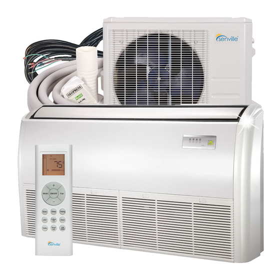
CEILING & FLOOR TYPE AIR CONDITIONER
Owner's Manual &
Installation Manual
IMPORTANT NOTE:
Read this manual carefully before installing
or operating your new air conditioning
unit. Make sure to save this manual for
future reference.
Please check the applicable models, technical
data, F-GAS(if any) and manufacturer information
from the "Owner's Manual - Product Fiche "
in the packaging of the outdoor unit.
(European Union products only)
SENA/18HF/IF
SENA/24HF/IF
Advertisement
Table of Contents

Related Manuals for Senville SENA/18HF/IF


Summary of Contents for Senville SENA/18HF/IF
- Page 1 CEILING & FLOOR TYPE AIR CONDITIONER Owner’s Manual & SENA/18HF/IF Installation Manual SENA/24HF/IF IMPORTANT NOTE: Read this manual carefully before installing or operating your new air conditioning unit. Make sure to save this manual for future reference. Please check the applicable models, technical data, F-GAS(if any) and manufacturer information from the “Owner's Manual - Product Fiche ”...
-
Page 2: Table Of Contents
Table of Contents Safety Precautions ................04 Owner’s Manual Unit Specifications and Features ............07 1. Indoor unit display ................................07 2. Operating temperature ..............................08 3. Other features ..................................09 Care and Maintenance ..............10 Troubleshooting ................12... - Page 3 Installation Manual Accessories ..................16 Installation Summary ..............17 Unit Parts ..................18 Indoor Unit Installation ..............19 1. Select installation location ............................19 2. Hang indoor unit ................................21 3. Drill wall hole for connective piping ..........................23 4. Connect drain hose ................................23 Outdoor Unit Installation ..............
-
Page 4: Safety Precautions
Safety Precautions Read Safety Precautions Before Operation and Installation Incorrect installation due to ignoring instructions can cause serious damage or injury. The seriousness of potential damage or injuries is classified as either a WARNING or CAUTION. CAUTION WARNING This symbol indicates the possibility of This symbol indicates the possibility of personnel injury or loss of life. - Page 5 CLEANING AND MAINTENANCE WARNINGS Turn o the device and disconnect the power before cleaning. Failure to do so can cause • electrical shock. Do not clean the air conditioner with excessive amounts of water. • Do not clean the air conditioner with combustible cleaning agents. Combustible cleaning agents •...
-
Page 6: Owner's Manual
WARNINGS FOR PRODUCT INSTALLATION 1. Installation must be performed by an authorized dealer or specialist. Defective installation can cause water leakage, electrical shock, or re. 2. Installation must be performed according to the installation instructions. Improper installation can cause water leakage, electrical shock, or re. (In North America,installation must be performed in accordance with the requirement of NEC and CEC by authorized personnel only.) 3. -
Page 7: Unit Specifications And Features
Unit Specifications and Features Indoor unit display Illustrations in this manual are for explanatory purposes. The actual shape of your indoor unit NOTE: may be slightly different. The actual shape shall prevail. This display panel on the indoor unit can be used to operate the unit in case the remote control has been misplaced or is out of batteries. -
Page 8: Operating Temperature
Operating temperature When your air conditioner is used outside of the following temperature ranges, certain safety protection features may activate and cause the unit to disable. Inverter Split Type FOR OUTDOOR UNITS COOL mode HEAT mode DRY mode WITH AUXILIARY 17°C - 32°C 0°C - 30°C 10°C - 32°C... -
Page 9: Other Features
Other features Default Setting Louver Angle Memory Function When the air conditioner restarts after a Some models are designed with a louver angle power failure, it will default to the factory memory function. When the unit restarts after a settings (AUTO mode, AUTO fan, 24°C (76°F)). power failure, the angle of the horizontal louvers This may cause inconsistencies on the remote will automatically return to the previous... -
Page 10: Care And Maintenance
Care and Maintenance Cleaning Your Indoor Unit Clean the air lter by vacuuming the surface or washing it in warm water with mild BEFORE CLEANING OR detergent. MAINTENANCE Rinse the lter with clean water and allow it to air-dry. DO NOT let the lter dry in ALWAYS TURN OFF YOUR AIR CONDITIONER direct sunlight. - Page 11 Maintenance – CAUTION Long Periods of Non-Use Before changing the lter or cleaning, • If you plan not to use your air conditioner for an turn o the unit and disconnect its power extended period of time, do the following: supply.
-
Page 12: Troubleshooting
Troubleshooting SAFETY PRECAUTIONS If any of the following conditions occurs, turn o your unit immediately! The power cord is damaged or abnormally warm • You smell a burning odor • The unit emits loud or abnormal sounds • A power fuse blows or the circuit breaker frequently trips •... - Page 13 Issue Possible Causes The outdoor unit The unit will make di erent sounds based on its current operating mode. makes noises Dust is emitted from The unit may accumulate dust during extended periods of non-use, which will be either the indoor or emitted when the unit is turned on.
- Page 14 Problem Possible Causes Solution Wait for the power to be restored Power failure The power is turned o Turn on the power The unit is not The fuse is burned out Replace the fuse working Replace batteries Remote control batteries are dead The Unit’...
- Page 15 ☆ 7 times ☆ ☆ 8 times Outdoor IPM temperature sensor error ☆ ☆(flash) O(light) X(off) Note: For additional information on how to further diagnose the error codes on the unit, you can go to our website: https://support.senville.com Page 15 ...
-
Page 16: Accessories
Accessories The air conditioning system comes with the following accessories. Use all of the installation parts and accessories to install the air conditioner. Improper installation may result in water leakage, electrical shock and re, or cause the equipment to fail. The items are not included with the air conditioner must be purchased separately. -
Page 17: Installation Summary
Installation Summary Install the indoor unit Install the drainpipe Install the outdoor unit Evacuate the refrigeration Connect the wires Connect the refrigerant system pipes Perform a test run Page 17 ... -
Page 18: Unit Parts
Unit Parts NOTE: The installation must be performed in accordance with the requirement of local and national standards. The installation may be slightly di erent in di erent areas. Air ow louver (at air outlet) Air inlet (with air lter in it) Installation part Display panel Remote controller... -
Page 19: Indoor Unit Installation
Indoor Unit Installation Installation Instructions – Indoor unit NOTE: Panel installation should be performed after piping and wiring have been completed. Step 1: Select installation location DO NOT install unit in the following Before installing the indoor unit, you must locations: choose an appropriate location. - Page 20 Refrigerant pipe connection (D. gas side) Drain point Refrigerant pipe connection (E. Liquid side) Hook Indoor model installation size MODEL(Btu/h) Length of A (mm/inch) Length of B (mm/inch) Length of C (mm/inch) Length of D (mm/inch) Length of E (mm/inch) 18K~24K 1068/42 675/26.6...
-
Page 21: Hang Indoor Unit
Step 2: Hang indoor unit (Mounting CAUTION hardware not included) The unit body must be completely aligned with Wood the hole. Ensure that the unit and the hole are the same size before moving on. Place the wood mounting across the roof beam, then install the threaded rods as shown. - Page 22 How to install the conduit installation plate 8. Remove the side board and the grille. (if supplied) Hanging Hanging arm 1. Fix the sheath connector (not supply) on the screw bolt wire hole of the conduit installation plate. 2. Fix the the conduit installation plate on the chassis of the unit.
-
Page 23: Drill Wall Hole For Connective Piping
Indoor Drainpipe Installation Step 3: Drill wall hole for connective piping 1. Determine the location of the wall hole Install the drainpipe as illustrated in the following based on the location of the outdoor unit. Figure. Using a 65mm (2.5in) or 90mm(3.54in) 1-1.5m (depending on models )core drill, drill a (39-59”) -
Page 24: Outdoor Unit Installation
Outdoor Unit Installation Install the unit by following local codes and install unit in the following locations: DO NOT regulations , there may be di er slightly Near an obstacle that will block air inlets between di erent regions. and outlets Near a public street, crowded areas, or where noise from the unit will disturb others Near animals or plants that will be harmed... -
Page 25: Install Drain Joint
Step 2: Install drain joint(Heat pump unit only) Step 3: Anchor outdoor unit Before bolting the outdoor unit in place, you must The outdoor unit can be anchored to the install the drain joint at the bottom of the unit. ground or to a wall-mounted bracket with Note that there are two di erent types of drain bolt(M10). - Page 26 Model Outdoor Unit Dimensions (inch) Mounting Dimensions Number W x H x D Di Distance A inch) Distance B (inch) 21.26" (540mm) 33.3”x27.6”x14.3” (845x702x363mm) 13.80" (350mm) SENA/18HF/OZ 37.2”x31.9”x16.1” (946x810x410mm) 26.50" (673mm) SENA/24HF/OZ 15.87" (403mm) Rows of series installation The relations between H, A and L are as follows. 25 cm / 9.8”...
-
Page 27: Refrigerant Piping Connection
Refrigerant Piping Connection When connecting refrigerant piping, do not let substances or gases other than the speci ed refrigerant enter the unit. The presence of other gases or substances will lower the unit’ s capacity, and can cause abnormally high pressure in the refrigeration cycle. This can cause explosion and injury. -
Page 28: Connection Instructions -Refrigerant Piping
2. Using a reamer or deburring tool, remove Connection Instructions – all burrs from the cut section of the pipe. Refrigerant Piping Pipe Reamer CAUTION The branching pipe must be installed • Point down horizontally. An angle of more than 10° may cause malfunction. -
Page 29: Connect Pipes
Place aring tool onto the form. Turn the handle of the aring tool clockwise until the pipe is fully ared. Flare the pipe in accordance with the dimensions. PIPING EXTENSION BEYOND FLARE FORM Outer Diameter A (inch) of Pipe (inch) Max. - Page 30 CAUTION Check to make sure there is no refrigerant leak Bend the pipe with thumb after completing the installation work. If there is a refrigerant leak, ventilate the area immediately and evacuate the system (refer to the Air Evacuation section of this manual). NOTE ON MINIMUM BEND RADIUS min-radius 10cm (3.9”) Carefully bend the tubing in the middle...
-
Page 31: Wiring
Wiring BEFORE PERFORMING ANY Make sure that you do not cross your electrical wiring with your signal wiring. ELECTRICAL WORK, READ THESE This may cause distortion and REGULATIONS interference. 1. All wiring must comply with local and national No other equipment should be electrical codes, regulations and must be connected to the same power circuit. -
Page 32: Indoor Uint Wiring
b. Using wire strippers, strip the rubber 3. Connect the u-lugs to the terminals. jacketfrom both ends of the signal cable Match the wire colors/labels with the labels on to reveal approximately 15cm (5.9”) of the terminal block, Firmly screw the u-lug of wire. - Page 33 Outdoor unit Indoor unit Black Black White White Black Grn/Yel Grn/Yel Interconnecting Grn/Yel Cable Main Power Cable Model Max Overcurrent Main Power Wire Minimum Circuit Voltage Protection (MOP) Size (AWG)* Amps (MCA) Number SENA/09HF/OZ 208/230V - 1ph 60Hz SENA/12HF/OZ 208/230V - 1ph 60Hz 208/230V - 1ph 60Hz SENA/18HF/OZ SENA/24HF/OZ...
-
Page 34: Air Evacuation
Air Evacuation Note that the service port has a Preparations and Precautions Schrader valve similar to a tire valve that Air and foreign matter in the refrigerant circuit will open and close when attaching and can cause abnormal rises in pressure, which removing the hose. -
Page 35: Note On Adding Refrigerant(R410A)
Inset a hex wrench into the valve and turn it OPEN VALVE STEMS GENTLY about a 1/4 turn to release some refrigerant into the system. Once the needle moves, close When opening valve stems, turn the hexagonal the valve. The system is now partially wrench until it hits against the stopper. -
Page 36: Test Run
Test Run f. Check to see that the drainage system is Before Test Run unimpeded and draining smoothly. A test run must be performed after the entire g. Ensure there is no vibration or abnormal system has been completely installed. Confirm noise during operation. - Page 37 The design and specifications are subject to change without prior notice for product improvement. Consult with the sales agency or manufacturer for details. Any updates to the manual will be uploaded to the service website, please check for the latest version.
Need help?
Do you have a question about the SENA/18HF/IF and is the answer not in the manual?
Questions and answers
What is the lowest temperature range I can set when I leave the house in sub-zero temperatures?
The lowest temperature setting for the Senville SENA/18HF/IF when leaving the house in sub-zero temperatures is 10°C (50°F) in heating mode.
This answer is automatically generated