Table of Contents
Advertisement
Quick Links
Advertisement
Table of Contents

Related Manuals for Exor gigaSOM gS01


Summary of Contents for Exor gigaSOM gS01
- Page 1 gigaSOM gS01Carrier HW Manual September 2019...
- Page 2 All rights, including rights created by patent grant or registration of a utility model or design, are reserved. Technical data subject to change. Copyright © 2019 EXOR International S.p.A. - All Rights Reserved. THW-EKGS01 - REV. 0.2 ©2019 EXOR Embedded S.r.l.
-
Page 3: Table Of Contents
Power ........................34 4.1.2 Reset ........................34 4.2 GPIO, SMB, I2C, PWM Header ..................34 4.3 LEDs, DIP Switches ......................35 4.4 JTAG ..........................37 THW-EKGS01 - REV. 0.2 ©2019 EXOR Embedded S.r.l. - Subject to change without notice exorint.com... - Page 4 Table 19. DIP Switch (S6) Configuration ......................35 Table 20. LED Status (0-7) Description ......................36 Table 21. DIP Switch (S5) Configuration ......................36 Table 22. JTAG Pinout ............................37 THW-EKGS01 - REV. 0.2 ©2019 EXOR Embedded S.r.l. - Subject to change without notice exorint.com...
-
Page 5: Introduction
Carrier board. This HW manual describes the gigaSOM carrier board. This document provides information about the features and communication interfaces available on gigaSOM Carrier. THW-EKGS01 - REV. 0.2 ©2019 EXOR Embedded S.r.l. - Subject to change without notice exorint.com... -
Page 6: Features
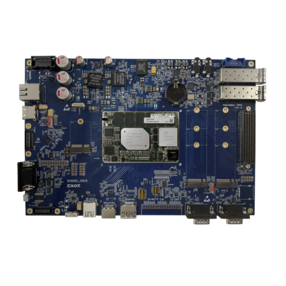
DIP switches, LEDs connector battery Audio interfaces interfaces JTAG M.2 key B SFP+ SIM card slots connector Interfaces Figure 2. The gigaSOM Carrier and Component Diagram THW-EKGS01 - REV. 0.2 ©2019 EXOR Embedded S.r.l. - Subject to change without notice exorint.com... - Page 7 EEPROM Temperature Sensor RTC Battery 2x CAN Interfaces FMC Connector 2x JTAG 2x SFP+ Interfaces 2x GPIO, DIP Switches Controlled LEDs SSW Connector 3x Buttons THW-EKGS01 - REV. 0.2 ©2019 EXOR Embedded S.r.l. - Subject to change without notice exorint.com...
-
Page 8: Block Diagram
Block Diagram This section shows the block diagram of gigaSOM carrier. Figure 3. Figure 3. Block Diagram THW-EKGS01 - REV. 0.2 ©2019 EXOR Embedded S.r.l. - Subject to change without notice exorint.com... -
Page 9: Gigasom Edge Pads
Internal left LAN_LED_ACT# TL19 External left USB2_N4 BL14 Internal left LAN_MDI1N TL20 External left USB2_P4 BL15 Internal left LAN_MDI1P TL21 External left BL16 Internal left THW-EKGS01 - REV. 0.2 ©2019 EXOR Embedded S.r.l. - Subject to change without notice exorint.com... - Page 10 Internal left UART2_TXD TL43 External left GPIO11 BL38 Internal left UART1_RTS TL44 External left GPIO10 BL39 Internal left UART1_CTS TL45 External left GPIO9 BL40 Internal left THW-EKGS01 - REV. 0.2 ©2019 EXOR Embedded S.r.l. - Subject to change without notice exorint.com...
- Page 11 Internal right F_FMC_LA_TXN11 External right Internal right F_FMC_LA_TXP11 External right F_FMC_LA_RXN11 Internal right TR10 External right F_FMC_LA_RXP11 Internal right F_SPI_CLK_1V5 TR11 External right F_FMC_LA_RXN15 Internal right THW-EKGS01 - REV. 0.2 ©2019 EXOR Embedded S.r.l. - Subject to change without notice exorint.com...
- Page 12 Internal right F_FMC_LA_TXP8 TR33 External right BR28 Internal right F_FMC_LA_TXN15 TR34 External right F_FMC_LA_RXN12 BR29 Internal right F_FMC_LA_TXP15 TR35 External right F_FMC_LA_RXP12 BR30 Internal right THW-EKGS01 - REV. 0.2 ©2019 EXOR Embedded S.r.l. - Subject to change without notice exorint.com...
- Page 13 TR53 External right TR54 External right F_FMC_LA_TXN4 TR55 External right F_FMC_LA_TXP4 TR56 External right F_FMC_LA_TXN3 TR57 External right F_FMC_LA_TXP3 TR58 External right 5VSB External top THW-EKGS01 - REV. 0.2 ©2019 EXOR Embedded S.r.l. - Subject to change without notice exorint.com...
- Page 14 External top SDIO_D1 TT20 External top SDIO_D2 TT21 External top SDIO_D3 TT22 External top SDIO_CMD TT23 External top SDIO_CLK TT24 External top TT25 External top THW-EKGS01 - REV. 0.2 ©2019 EXOR Embedded S.r.l. - Subject to change without notice exorint.com...
- Page 15 External top SATA_LED_N TT44 External top LPSS_I2C0_SDA TT45 External top LPSS_I2C0_SCL TT46 External top LPSS_I2C1_SDA TT47 External top LPSS_I2C1_SCL TT48 External top LPSS_I2C2_SDA TT49 External top THW-EKGS01 - REV. 0.2 ©2019 EXOR Embedded S.r.l. - Subject to change without notice exorint.com...
- Page 16 External top AVS_I2S1_SDO TT68 External top AVS_I2S1_BCLK TT69 External top VCC_ADJ_F TT70 External top VCC_ADJ_F TT71 External top VCC_ADJ_F TT72 External top VCC_ADJ_F TT73 External top THW-EKGS01 - REV. 0.2 ©2019 EXOR Embedded S.r.l. - Subject to change without notice exorint.com...
- Page 17 External SOC_PWM1 bottom External SOC_PWM0 bottom External bottom External Internal SATA_RXN1 GPIO8 bottom bottom External Internal SATA_RXP1 bottom bottom External Internal SATA_TXN1 SIO_SPI1_FS0 bottom bottom THW-EKGS01 - REV. 0.2 ©2019 EXOR Embedded S.r.l. - Subject to change without notice exorint.com...
- Page 18 External Internal DDI1_TXN1 TB30 MCSI_RX_CLK0_N BB25 bottom bottom External Internal DDI1_TXP1 TB31 MCSI_RX_CLK0_P BB26 bottom bottom External Internal DDI1_TXN0 TB32 BB27 bottom bottom THW-EKGS01 - REV. 0.2 ©2019 EXOR Embedded S.r.l. - Subject to change without notice exorint.com...
- Page 19 External Internal PCIE_CLKREQ3# TB54 BB49 bottom bottom External Internal PCIE1_RESET TB55 PCIE_P2_RXN BB50 bottom bottom External Internal PCIE_WAKE2# TB56 PCIE_P2_RXP BB51 bottom bottom THW-EKGS01 - REV. 0.2 ©2019 EXOR Embedded S.r.l. - Subject to change without notice exorint.com...
- Page 20 External Internal F_SFP_INT0 TB76 F_FMC_LA_RXP1 BB71 bottom bottom External F_VREF_FMC TB77 bottom External FMC_PRENT TB78 bottom External TB79 bottom External 1V5_MEM_F TB80 bottom THW-EKGS01 - REV. 0.2 ©2019 EXOR Embedded S.r.l. - Subject to change without notice exorint.com...
-
Page 21: Temperature Range
The gigaSOM carrier provides a board-mounted battery holder (BAT1) for a RTC battery. The RTC battery supplies the power required to maintain the module RTC memory. The required battery type on gigaSOM carrier is CR2032 THW-EKGS01 - REV. 0.2 ©2019 EXOR Embedded S.r.l. - Subject to change without notice exorint.com... -
Page 22: Fan Connector
Description +5V_FAN Output voltage (5V) Ground Table 3. FAN Connector Description Mechanical Dimensions Figure 4. shows the dimension of gigaSOM carrier. Figure 4. Mechanical Dimensions THW-EKGS01 - REV. 0.2 ©2019 EXOR Embedded S.r.l. - Subject to change without notice exorint.com... -
Page 23: Interfaces
Slide Configuration Switch Enable USB 2.0 Header, disable USB 2.0 QSH Enable USB 2.0 QSH, disable USB 2.0 Header Table 5. Slide Switch S1 Description THW-EKGS01 - REV. 0.2 ©2019 EXOR Embedded S.r.l. - Subject to change without notice exorint.com... -
Page 24: Usb 2.0 Debug Port
LVDS_A3_N Differantial Data Negative LVDS Channel A +3V3 Output voltage (3V3) LVDS_A3_P Differantial Data Positive +3V3 Output voltage (3V3) Ground +3V3 Output voltage (3V3) Ground THW-EKGS01 - REV. 0.2 ©2019 EXOR Embedded S.r.l. - Subject to change without notice exorint.com... -
Page 25: Gigabit Ethernet
The gigaSOM carrier features two audio codecs HDA (CS4207) and I2S (WM8904). Each codecs suport Line-out signals and MIC-in signals on 3.5 mm audio jacks (J15 for I2S codec and J16 for HDA codec). THW-EKGS01 - REV. 0.2 ©2019 EXOR Embedded S.r.l. - Subject to change without notice exorint.com... -
Page 26: Csi Interface
CSI RX Differantial Data No Connect Positive SOC_CSI_RX CSI RX Differantial Data No Connect Negative Output voltage (1V8) 1V8A Ground from CPU No Connect Ground THW-EKGS01 - REV. 0.2 ©2019 EXOR Embedded S.r.l. - Subject to change without notice exorint.com... -
Page 27: Serial Port
RS485 mode, controlled by RTS RS232 mode, controlled by RTS RS485 mode, controlled by CPU RS232 mode, controlled by RTS Table 8. DIP Switch S2 Description THW-EKGS01 - REV. 0.2 ©2019 EXOR Embedded S.r.l. - Subject to change without notice exorint.com... -
Page 28: Lpc Bus
Data Output pin for the SOC_SPI_TXD Ground processor SPI Clock signal Ground SOC_SPI_CLK Used as the SPI bus SOC_SPI_FS1 Ground request signal Table 10. SPI Header Description THW-EKGS01 - REV. 0.2 ©2019 EXOR Embedded S.r.l. - Subject to change without notice exorint.com... -
Page 29: Pcie
The gigaSOM carrier provides an M.2 Key E slot (J20) for connecting Wifi, NFC, GNSS and Bluetooth devices. The M.2 connector (J20) suports multiple interfaces USB 2.0, PCIe, SDIO, UART, I2C, I2S. THW-EKGS01 - REV. 0.2 ©2019 EXOR Embedded S.r.l. - Subject to change without notice exorint.com... -
Page 30: Sata
Bank H Bank G Bank D Bank C +VREF_FMC FMC_PG_C2M FMC_PRSNT FMC_CLK0_M2C_P FMC_DP0_C2M_P FMC_CLK0_M2C_N FMC_DP0_C2M_N FMC_CLK1_M2C_P GBTCLK0_M2C_P FMC_CLK1_M2C_N GBTCLK0_M2C_N FMC_LA_CC0_P FMC_DP0_M2C_P FMC_LA_TX0_P FMC_LA_CC0_N FMC_DP0_M2C_N FMC_LA_TX0_N FMC_LA_CC1_P THW-EKGS01 - REV. 0.2 ©2019 EXOR Embedded S.r.l. - Subject to change without notice exorint.com... - Page 31 FMC_LA_TX13_P FMC_TDI FMC_I2C_SCL FMC_LA_TX15_P FMC_LA_TX13_N FMC_TDO FMC_I2C_SDA FMC_LA_TX15_N +3V3 FMC_LA_TX8_P FMC_TMS FMC_LA_TX12_P FMC_LA_TX8_N FMC_TRSTn FMC_GA0 FMC_LA_TX12_N FMC_GA1 +12V_CONN FMC_LA_TX10_P +3V3 FMC_LA_TX7_P FMC_LA_TX10_N +12V_CONN FMC_LA_TX7_N +3V3 THW-EKGS01 - REV. 0.2 ©2019 EXOR Embedded S.r.l. - Subject to change without notice exorint.com...
-
Page 32: Fmc Jtag
UART Data Output EXT_GPIO4 Expander GPIO Signal from I/O UART3_RX UART Data Input EXT_GPIO3 Expander GPIO Signal from I/O UART3_RTS UART Ready to Send EXT_GPIO2 Expander THW-EKGS01 - REV. 0.2 ©2019 EXOR Embedded S.r.l. - Subject to change without notice exorint.com... -
Page 33: Table 16. Ssw Connector Description
Output voltage (1V8) +12V_CONN Output voltage (12V) +3V3 Output voltage (3V3) Output voltage (5V) +3V3 Output voltage (3V3) Output voltage (5V) Table 16. SSW Connector Description THW-EKGS01 - REV. 0.2 ©2019 EXOR Embedded S.r.l. - Subject to change without notice exorint.com... -
Page 34: Additional Features
Ground Expander (3V3) EXT_CPU_GPI I2C3_SDA_3V GPIO Signal from I/O I2C Data (3V3) Expander (3V3) EXT_CPU_GPI I2C3_SCL_3V GPIO Signal from I/O I2C Clock (3V3) Expander (3V3) THW-EKGS01 - REV. 0.2 ©2019 EXOR Embedded S.r.l. - Subject to change without notice exorint.com... -
Page 35: Leds, Dip Switches
GPIO_2 is DOWN when SW3 is turn ON EXD_FPGA_GPIO_3 GPIO_3 is DOWN when SW4 is turn ON EXD_FPGA_GPIO_4 GPIO_4 is DOWN when SW5 is turn ON Table 19. DIP Switch (S6) Configuration THW-EKGS01 - REV. 0.2 ©2019 EXOR Embedded S.r.l. - Subject to change without notice exorint.com... -
Page 36: Table 20. Led Status (0-7) Description
GPI_5 is DOWN when SW6 is turn ON GPI_6 GPI_6 is DOWN when SW7 is turn ON GPI_7 GPI_7 is DOWN when SW8 is turn ON Table 21. DIP Switch (S5) Configuration THW-EKGS01 - REV. 0.2 ©2019 EXOR Embedded S.r.l. - Subject to change without notice exorint.com... -
Page 37: Jtag
JTAG Data Out Output voltage (1V8) +1V8 FMC_TMS JTAG Mode Select No Connect No Connect No Connect FMC_TDI JTAG Data In Ground Table 22. JTAG Pinout THW-EKGS01 - REV. 0.2 ©2019 EXOR Embedded S.r.l. - Subject to change without notice exorint.com...
Need help?
Do you have a question about the gigaSOM gS01 and is the answer not in the manual?
Questions and answers