Table of Contents
Advertisement
Quick Links
Advertisement
Table of Contents

Related Manuals for Exor GigaSOM gS01


Summary of Contents for Exor GigaSOM gS01
- Page 1 GigaSOM gS01 Evaluation kit December 2019...
- Page 2 All rights, including rights created by patent grant or registration of a utility model or design, are reserved. Technical data subject to change. Copyright © 2019 EXOR International S.p.A. - All Rights Reserved. Evaluation kit - REV. 0.2 ©2019 EXOR Embedded S.r.l.
-
Page 3: Table Of Contents
6.16 CAN interface ........................12 6.17 FMC connector ....................... 12 6.17.1 FMC JTAG ......................13 6.18 JTAG 6.19 SFP+ 6.20 SSW connector ....................... 14 Evaluation kit - REV. 0.2 ©2019 EXOR Embedded S.r.l. - Subject to change without notice exorint.com... -
Page 4: Introduction
Cyclone 10 GX FPGA Kit Contents • GigaSOM Carrier Board • GigaSOM Module • SD card with preloaded starting Linux OS • Power supply adapter Evaluation kit - REV. 0.2 ©2019 EXOR Embedded S.r.l. - Subject to change without notice exorint.com... -
Page 5: This Is Gigasom
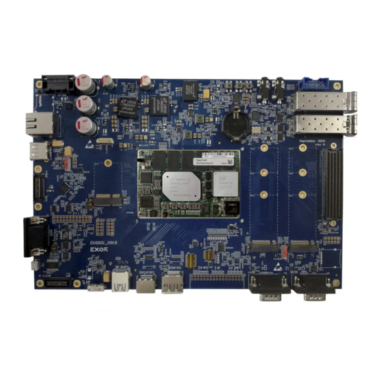
This is GigaSOM Figure: GigaSOM Carrier Board and GigaSOM module Evaluation kit - REV. 0.2 ©2019 EXOR Embedded S.r.l. - Subject to change without notice exorint.com... -
Page 6: Carrier Connectors And Interfaces
Audio interfaces interfaces JTAG M.2 key B SFP+ SIM card slots connector Interface Figure: Interfaces and connectors on GigaSOM Carrier Board Evaluation kit - REV. 0.2 ©2019 EXOR Embedded S.r.l. - Subject to change without notice exorint.com... -
Page 7: Getting Started
GigaSOM module i.e. CPU when pressed (warm boot). Button S8 is a system reset button and will reset GigaSOM board when pressed (cold boot). Button S9 is reserved and it is not used. Evaluation kit - REV. 0.2 ©2019 EXOR Embedded S.r.l. - Subject to change without notice exorint.com... -
Page 8: Usb
LQ156M3LW01 display with LVDS interface. It requires QSH to LVDS adapter. WARNING: Be careful not to connect the display to camera connector J8. They both use the same QSH connector. Evaluation kit - REV. 0.2 ©2019 EXOR Embedded S.r.l. - Subject to change without notice exorint.com... -
Page 9: Ethernet
4 metal rings on it i.e. needs to have tip, two rings and a sleeve. Figure: HDA (left) and I2S (right) 3.5 mm sockets Evaluation kit - REV. 0.2 ©2019 EXOR Embedded S.r.l. - Subject to change without notice exorint.com... -
Page 10: Spi Interface
Camera can be connected on CSI interface QSH connector J8. It requires QSH to CSI adapter. WARNING: Be careful not to connect the camera to LVDS connector J7. They both use the same QSH connector. Figure: QSH CSI connector Evaluation kit - REV. 0.2 ©2019 EXOR Embedded S.r.l. - Subject to change without notice exorint.com... -
Page 11: Serial Interface
2242, 2260, and 2280. The Switch S3 can be used to change slot J17 to work with PCIe or SATA interface. Figure: M.2 key B slots. J17 is the bottom and J19 is the top one Evaluation kit - REV. 0.2 ©2019 EXOR Embedded S.r.l. - Subject to change without notice exorint.com... -
Page 12: Key E Slot
There is an FMC connector at the J25. It’s a Low Pin Count (LPC) connector size. Only Bank A is connected on the board and any connector with Bank A connection is supported. Evaluation kit - REV. 0.2 ©2019 EXOR Embedded S.r.l. - Subject to change without notice exorint.com... -
Page 13: Fmc Jtag
There is an FMC JTAG connector at J26. 6.18 JTAG There is a JTAG connector at J30. This is used for programming and debugging GigaSOM module. Figure: JTAG connector Evaluation kit - REV. 0.2 ©2019 EXOR Embedded S.r.l. - Subject to change without notice exorint.com... -
Page 14: Sfp
There is an SSW Samtec connector at J27. It can be used with multiple interfaces such as SPI, UART, I2C, two groups of GPIO signals and power supply. Evaluation kit - REV. 0.2 ©2019 EXOR Embedded S.r.l. - Subject to change without notice exorint.com...
Need help?
Do you have a question about the GigaSOM gS01 and is the answer not in the manual?
Questions and answers