
Related Manuals for I-Gard IPC GEMINI


Summary of Contents for I-Gard IPC GEMINI
- Page 1 g E M I N I hIgh RESISTANCE gROUNDINg SYSTEM the power to protect Instruction Manual C -102...
- Page 2 HIGH RESISTANCE GROUNDING SYSTEM Gemini is a unique, fail safe, all-in-one neutral grounding system, combining ground fault protection with a redundant resistor system, in addition to a built-in resistor integrity monitoring relay. Providing protection against any compromising of the resistor integrity, the patented twin resistance paths in combination with the integrity monitoring relay form the heart of the Gemini system.
-
Page 3: Table Of Contents
TAblE Of CONTENTS 1 general Description 2 Installation 3 Operation 4 Maintenance 5 Appendix 1 5.1 High-Resistance Grounding 5.2 Definitions and Applicable Standards 6 Additional Information 7 Instruction Manuals TAblE Of fIGURES Figure 1 Close up of Front Panel Figure 2 Wiring Diagram for Gemini Figure 3 Outside Dimensions Figure 4 Outside Dimensions Figure 5 Gemini Control Panel Figure 6 GFR-RM Dipswitch TAblES Table 1 GFR-RM Default Settings Gemini Instruction Manual I-GARD... -
Page 4: General Description
A versatile ground fault relay I-Gard Type GFR-RM in the Gemini system indicates the presence of ground faults that may occur on the power system by current measurement within the Gemini unit itself, in addition to providing a monitor that will operate a local and remote Alarm if the value of the Grounding resistor elements changes to a lower or higher limit set by the user. -
Page 5: Installation
On receipt, carefully open the protective shipping carton, remove all packing material and visually inspect the unit. If the unit is damaged do not proceed with installation. Contact I-Gard at the numbers listed on the final page of this document. -
Page 6: Figure 2 Wiring Diagram For Gemini
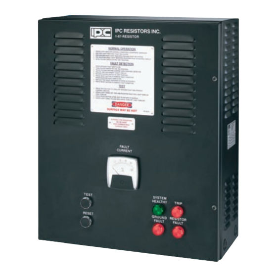
GREEN LIGHT TURNS ON, RED AND AMBER LIGHTS TURN OFF. 24" FAULT CURRENT INDICATING LIGHTS SYSTEM TEST TRIP HEALTHY Ø7/8" RESET GROUND RESISTOR PROVISION FAULT FAULT FOR 1/2" CONDUIT 1 1/2" 1 3/4" 8 1/4" 1/4" 20" Figure 3 Outside Dimensions I-GARD Gemini Instruction Manual... -
Page 7: Figure 4 Outside Dimensions
Following installation, always perform a final inspection. All foreign objects must be removed. All conductors must be secured in the proper positions before closing the door and energizing the system. DO NOT ENERGIZE the Gemini unless the door is closed and secured by the two bolts provided. Gemini Instruction Manual I-GARD... -
Page 8: Operation
Both ground fault pickup level and time delay are adjusted using the bank of Dipswitches located on the front plate of the GFR-RM relay, which is located inside the Gemini enclosure. (Refer to I-Gard Manual IM-GFR-RM) for complete details of this relay). -
Page 9: Maintenance
Gemini is designed and constructed to operate properly with minimal maintenance, however, it is recommended that it be tested on a regular basis at a minimum of once every six months. The self-test feature allows for a rapid and reliable test. Gemini Instruction Manual I-GARD... - Page 10 The exterior may be cleaned using a slightly damp cloth. Ensure that the Gemini is completely dry before energizing. Close the front door and reconnect electrical power. Test the unit again before returning to normal service. I-GARD Gemini Instruction Manual...
-
Page 11: Appendix
Bonding means a low impedance path obtained by permanently joining all non-current-carrying metal parts to assure electrical continuity and having the capacity to conduct safely any current likely to be imposed on it; Gemini Instruction Manual I-GARD... - Page 12 CSa Canadian electrical Code Part 1, C22.1-98 Pg. 105-106 10-1100 Scope. Rules 10-1102 to 10-1108 apply to the use of neutral grounding devices used for the purpose of controlling the ground fault current or the voltage to ground of an alternating-current system. I-GARD Gemini Instruction Manual...
- Page 13 ) Identified white or natural grey; and c ) Sized to conduct the rated current of the neutral grounding device, and in no case less than No. 8 AWG; and d ) Installed in accordance with other appropriate Rules of this Code. Gemini Instruction Manual I-GARD...
-
Page 14: Additional Information
ADDITIONAl INfORMATION If you require more information or experience problems with your equipment that persist after taking the steps identified in this manual, contact I-Gard customer service. I-GARD Gemini Instruction Manual... -
Page 15: Instruction Manuals
INSTRUCTION MANUAlS C-101 Stoplight C-102 Gemini C-105 Fusion High Resistance Grounding High Resistance Grounding Ground Fault Protection System Manual System Manual System Manual C-322 MGFR C-407 GCHK-100 Mining Relay C-408 Sleuth Ground Fault Relay Manual Ground Fault Protection High Resistance System Manual Grounding System Manual C-409 DSP OHMNI... - Page 16 7615 Kimbel St., Unit 1 Mississauga, Ontario Canada L5S 1A8 Phone 905-673-1553 Toll Free 1-800-737-4787 905-673-8472 e-mail: sales@i-gard.com www.i-gard.com...
Need help?
Do you have a question about the IPC GEMINI and is the answer not in the manual?
Questions and answers