Table of Contents

Related Manuals for Alnor MANDIK FDMC

Summary of Contents for Alnor MANDIK FDMC
- Page 1 ® E N 1 5 6 5 0 : 2 0 1 0 A L N O R S y s t e my We n t y l a c j i S p . z o . o . A l e j a K r a k o w s k a 1 0 , 0 5 - 5 5 2 Wo l a Mr o k o w s k a t e l .
-
Page 2: Table Of Contents
TPM 083/12 These technical specifications state a row of manufactured sizes and models of fire dampers (further only dampers) FDMC. It is valid for production, designing, ordering, delivery, assembly and operation. I. CONTENT II. GENERAL INFORMATION 1. Description......................... 2. Design..........................3. -
Page 3: General Information
TPM 083/12 II. GENERAL INFORMATION 1. Description 1.1. Fire dampers are shutters in piping systems of air-conditioning devices that prevent spreading the fire and combustion products from one fire segment to the other one by means of closing the air piping in the points of fire separating constructions. 1.2. -
Page 4: Design
TPM 083/12 2. Design 2.1. Actuating mechanism 2.1.1. Design with an actuating mechanism BLF 24-T or BLF 230-T (further only "actuating mechanism"). After being connected to power supply AC/DC 24V or 230V, the actuating mechanism displaces the damper blade into operation position "OPEN" and at the same time it pre-stretches its back spring. - Page 5 TPM 083/12 Except for reporting failures, other three auxiliary contacts are available. Contacts showing operating and failure position of the flap valve are active when the flap valve is in the given position. Function check can be done by pressing and holding the button "RESET/TEST" for longer time. While holding the button, the flap blade moves in the direction of the failure position.
-
Page 6: Dimensions, Weights
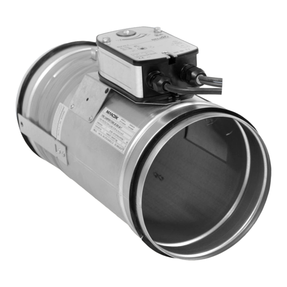
TPM 083/12 Fig. 1 3. Dimestions, weights 3.1. Dimensions Fig. 2 Fire damper FDMC Position: Damper body BAE 72B-S thermoelectrical starting mechanism Damper blade Inspection hole covering Actuating mechanism... -
Page 7: Placement And Assembly
TPM 083/12 3.2. Weight and effective area Tab. 3.2.1. Weight and effective area Size Weight Actuating mechanism Effective area 0,0036 0,0068 0,0092 0,0109 0,0129 0,0172 0,0222 0,0293 0,0374 0,0484 41,5 0,0630 0,0793 61,5 0,0821 0,1065 3.3. For fire damper the open damper blade overlaps the damper body from dimension 250 by the “a”... - Page 8 TPM 083/12 4.2. To provide needed access space to the control device, all other objects must be situated at least 350 mm from the control parts of the damper. Inspection hole must be accessible. 4.3. The distance between the fire damper and the construction (wall, ceiling) must be minimum 75 mm.
-
Page 9: Statement Of Installations
TPM 083/12 5. Statement of installations 5.1. Statement of installations Tab. 5.1.1. Statement of installations Classifi- Size FDMC installation Figure cation Damper installed in a solid wall construction min. thickness 100 mm. EIS 60 Space between damper and wall is filled by mortar, gypsum. 100-400 Damper installed in a gypsum wall construction - fire classification EI 90. -
Page 10: Technical Data
TPM 083/12 Fig. 9 Damper installed on a ceiling wall construction Position: Fire damper FDMC Mortar or gypsum with min. density 800 kg/m III. TECHNICAL DATA 6. Pressure loss 6.1. Pressure loss calculation [Pa] presure loss [m.s air flow speed in nominal damper section [kg.m air density coefficient of local pressure loss for the nominal damper section... -
Page 11: Coefficient Of Local Pressure Loss
TPM 083/12 7. Coefficient of local pressure loss 7.1. Coefficient of local pressure loss Tab. 7.1.1. Coefficient of local pressure loss 2,736 2,099 1,781 1,527 1,272 0,929 0,636 0,477 0,344 0,237 0,159 0,125 0,116 0,085 8. Noise data 8.1. Level of acoustic output corrected with filter A. + 10 log(S) + K [dB(A)] level of acoustic output corrected with filter A [dB]... - Page 12 TPM 083/12 Tab. 8.3.2. Correction to the weight filter A w [m.s [dB] -15,0 -11,8 -9,8 -8,4 -7,3 -6,4 -5,7 -5,0 -4,5 -4,0 -3,6 Tab. 8.3.3. Relative level expressing the shape of the spectrum L f [Hz] w [m.s 1000 2000 4000 8000...
-
Page 13: Electrical Components, Connection Diagrams
TPM 083/12 9. Electrical Components, Connection Diagrams 9.1. Actuating mechanism Tab. 9.1.1. Actuating mechanism BELIMO BLF 24-T(-ST), BLF 230-T Actuating mechanism BELIMO BLF 24-T-ST(24-ST) BLF230-T AC 230 V 50/60Hz Nominal voltage AC 24V 50/60Hz DC 24 V Power consumption - motoring - holding 2,5 W 7 VA (Imax 150 mA @ 10 ms) - Page 14 TPM 083/12 9.2. Communication and Supply Device Tab. 9.2.1. Communication and Supply Device BKN 230-24 Communication and Supply Device BKN 230-24 Nominal voltage AC 230V 50/60Hz Power consumption 3,5 W (operating position) Dimensioning 11 VA (including actuating mechanism) Protection Class Degree of protection IP 42 Ambient Temperature...
- Page 15 TPM 083/12 Fig. 16 Communication and Control Device BKS 24-1B Tab. 9.3.2. Communication and Control Device BKS 24-9A BKS 24-9A Communication and Control Device Nominal voltage AC 24 V 50/60Hz Power consumption 3,5 W (operating position) Dimensioning 5,5 VA Protection Class III (safe small voltage) Degree of protection IP 30...
-
Page 16: Ordering Information
TPM 083/12 Fig. 17 Communication and Control Device BKS 24-9A IV. ORDERING INFORMATION 10. Ordering key FDMC 180 - .40 TPM 083/12 technical specifications design acc. dle Tab. 2.3.1. size type V. DATA OF THE PRODUCT 11. Data label 11.1. Data label is placed on the body of fire damper. -
Page 17: Material, Finishing
TPM 083/12 VI. MATERIAL, FINISHING 12. Material 12.1. Damper bodies are supplied in the design made of galvanized plate without any other surface finish. 12.2. Damper blades are made of fire resistant asbestos free boards made of mineral fibres. 12.3. Fasteners is galvanized. - Page 18 TPM 083/12 16.1.2. Results of regular checks, imperfections found and all-important facts connected with the damper function must be recorded in the "FIRE BOOK" and immediately reported to the operator. 16.2. Before entering the dampers into operation after their assembly and by sequential checks, the following checks must be carried out.
- Page 19 TPM 083/12...
- Page 20 Wy ł ą c z n y D y s t r y b u t o r P r o d u c e n t A L N O R S y s t e my We n t y l a c j i S p . z o . o . A l e j a K r a k o w s k a 1 0 0 5 - 5 5 2 Wo l a M r o k o w s k a P o l s k a...
Need help?
Do you have a question about the MANDIK FDMC and is the answer not in the manual?
Questions and answers