Advertisement
Available languages
Available languages
Quick Links
EVCO S.p.A. | EVIF25TWX | Instruction sheet ver. 1.0 | Code 104IF25TWXA103 | Page 1 of 2 | PT 44/18
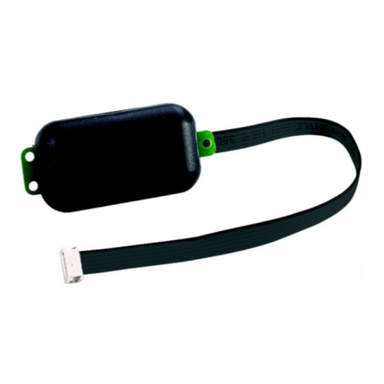
EVIF25TWX/EVIF25SWX
EN
ENGLISH
-
powered by the controller or 12 VAC/15 VDC power supply
-
clock
-
TTL MODBUS port or RS-485 MODBUS port (according to the model)
-
Wi-Fi connectivity.
Available models
Purchasing codes
Communication port
EVIF25TWX
TTL MODBUS
EVIF25SWX
RS-485 MODBUS
Installer manual
1
MEASUREMENTS AND INSTALLATION
Measurements in mm (inches); to be fitted on rigid support, with cable tie (not provided).
INSTALLATION PRECAUTIONS
-
Ensure that the working conditions are within the limits stated in the TECHNICAL
SPECIFICATIONS section
Do not install the device close to heat sources, equipment with a strong magnetic field,
-
in places subject to direct sunlight, rain, damp, excessive dust, mechanical vibrations
or shocks
-
In compliance with safety regulations, the device must be installed properly to ensure
adequate protection from contact with electrical parts. All protective parts must be
fixed in such a way as to need the aid of a tool to remove them.
2
ELECTRICAL CONNECTION
N.B.
- The compatibility of the controller with the remote monitoring system EPoCA and
the possibility to power EVlink Wi-Fi from the controller depends on the kind of
controller. Consult the document "EPoCA - List of compatible controllers" available
on the web site www.evco.it and/or the controller label
- If EVlink Wi-Fi must be powered with independent power supply, do not power it
with the same power source of the controller connected to EVlink Wi-Fi
- The battery of EVlink Wi-Fi is charged by the power supply of the device or by the
independent power supply: for correct operation, the battery must be fully charged
at least once a year
- To reduce any electromagnetic interference connect the power cables as far away
as possible from the signal cables and make the RS-485 connection by using a
twisted pair.
2.1
Example of electrical connection to a controller with TTL MODBUS port
In this example the controller is capable of powering the device.
In this example the controller is not capable of powering the device.
EVlink Wi-Fi module
2.2
Example of electrical connection to a controller with RS-485 MODBUS port
In this example the controller is capable of powering the device.
Connectivity
Wi-Fi
Wi-Fi
In this example the controller is not capable of powering the device.
PRECAUTIONS FOR ELECTRICAL CONNECTION
-
If the device has been moved from a cold to a warm place, the humidity may have
caused condensation to form inside. Wait about an hour before connecting it to the
controller
-
Disconnect the device from the controller before doing any type of maintenance
-
For repairs and for further information, contact the EVCO sales network.
3
MEANING OF LEDS
LED
ON
MODBUS
-
(L1, red)
Wi-Fi
connection both
(L2, green)
to
the
network and to
the Cloud server
4
FIRST-TIME USE
1.
Install following the instructions given in the section MEASUREMENTS AND INSTALLA-
TION.
2.
Power up the controller; see the relative instruction sheet.
3.
Configure the controller.
Recommended configuration parameters for first-time use.
PAR.
DEF.
PARAMETER
bLE
1
enable EVlink
rE0
15
data-logger sampling interval
rE1
- - -
recorded data
4.
Disconnect the controller from the mains.
5.
Connect the MODBUS port of the device to the MODBUS port of the controller as shown
in the section ELECTRICAL CONNECTION.
6.
If the device needs independent power supply, power up the device.
7.
Power up the controller and an internal test will be run.
The test normally takes a few seconds, when it is finished the LED of the device will
switch off.
8.
If the controller shows the label "rtc" flashing, set the date and time.
Do not disconnect the controller from the mains in the two minutes following the setting
of the date and time.
9.
Activate the Wi-Fi of a mobile device, localize the network called "Epoca" followed by a
suffix made of 6 number and letters (for example "Epoca279A62") and connect it to
the mobile device using password "epocawifi"; always verify the password on the label
of the device.
10.
For more information see the Installer manual.
5
TECHNICAL SPECIFICATIONS
Container:
Category of heat and fire resistance:
Measurements:
176.0 x 30.0 x 25.0 mm (6 15/16 x 1 3/16 x
1 in) the models with TTL MODBUS port
Mounting methods for the control device:
Degree of protection provided by the cover-
ing:
Connection method:
Removable screw terminal block for wires up
to 1,5 mm² and Pico-Blade connector for the
models with TTL MODBUS port
Maximum permitted length for connection cables:
Power supply: 10 m (32.8 ft)
Operating temperature:
Storage temperature:
Operating humidity:
Compliance:
RoHS 2011/65/CE
REACH (EC) Regulation no. 1907/2006
Power supply:
Software class and structure:
Clock:
Clock drift:
OFF
SLOW FLASHING
QUICK
SHING
no MODBUS ac-
MODBUS activity
-
tivity
-
no connection to
connection
Wi-Fi
the
Wi-Fi
net-
the
Wi-Fi
work
work, no connec-
tion to the Cloud
server
MIN... MAX.
0 = no
1 = yes
0... 240 min
according to the controller
Black, self-extinguishing.
D.
56.0 x 30.0 x 25.0 mm (2 3/16 x 1 3/16 x 1
in) the models with RS-485 MODBUS port.
On rigid support, with cable tie (not provid-
ed).
IP00.
Removable screw terminal block for wires up
to 1,5 mm² for the models with RS-485
MODBUS port.
RS-485 MODBUS port: 1,000 m (3,280 ft).
From 0 to 55 °C (from 32 to 131 °F).
From -25 to 70 °C (from -13 to 158 °F).
Relative humidity without condensate from 5
to 95%.
WEEE 2012/19/EU
RED 2014/53/EU.
powered by the controller or 12 VAC ±15 o
15 VDC ±15%, 50/60 Hz (±3 Hz), max.
3.2 VA/2W.
A.
Secondary lithium battery.
≤ 60s/month at 25°C (77 °F).
Clock battery autonomy in the absence of a
power supply:
Clock battery charging time:
Displays:
Communications ports:
Connectivity:
Wi-Fi output power (EIRP):
Wi-Fi frequency range:
I
ITALIANO
-
alimentato dal controllore o alimentazione 12 VAC/15 VDC
-
orologio
-
porta TTL MODBUS o RS-485 MODBUS (a seconda del modello)
-
connettività Wi-Fi.
Modelli disponibili
Codici di acquisto
Porta di comunicazione
EVIF25TWX
TTL MODBUS
EVIF25SWX
RS-485 MODBUS
Manuale installatore
1
DIMENSIONI E INSTALLAZIONE
Dimensioni in mm (in); installazione su supporto rigido, con fascetta stringicavo (non in dota-
zione).
AVVERTENZE PER L'INSTALLAZIONE
-
accertarsi che le condizioni di lavoro rientrino nei limiti riportati nel capitolo DATI TEC-
NICI
FLA-
-
non installare il dispositivo in prossimità di fonti di calore, di apparecchi con forti ma-
gneti, di luoghi soggetti alla luce solare diretta, pioggia, umidità, polvere eccessiva, vi-
brazioni meccaniche o scosse
-
in conformità alle normative sulla sicurezza, la protezione contro eventuali contatti con
le parti elettriche deve essere assicurata mediante una corretta installazione; tutte le
to
parti che assicurano la protezione devono essere fissate in modo tale da non poter es-
net-
sere rimosse senza l'aiuto di un utensile.
2
COLLEGAMENTO ELETTRICO
ATTENZIONE
- la compatibilità del controllore con il sistema di monitoraggio remoto EPoCA e la
possibilità di alimentare EVlink Wi-Fi dal controllore è subordinata al tipo di control-
lore. Consultare il documento "EPoCA - Elenco dei controllori compatibili" disponibi-
le sul sito www.evco.it e/o l'etichetta del controllore
- se EVlink Wi-Fi deve disporre di alimentazione autonoma, non alimentarlo con la
stessa fonte di alimentazione del controllore collegato a EVlink Wi-Fi
- la batteria di EVlink Wi-Fi viene caricata dall'alimentazione del dispositivo o dall'a-
limentazione autonoma: per il suo corretto funzionamento, la batteria deve essere
caricata completamente almeno una volta all'anno
- per ridurre eventuali disturbi elettromagnetici, collocare i cavi di potenza il più lon-
tano possibile da quelli di segnale ed eseguire il collegamento RS-485 utilizzando
un doppino twistato.
2.1
Esempio di collegamento elettrico a un controllore con porta TTL MODBUS
In questo esempio il controllore è in grado di alimentare il dispositivo.
> 6 months at 25 °C (77 °F).
24h (the battery is charged by the power
supply of the device).
For correct operation, the battery must be
fully charged at least once a year.
MODBUS and Wi-Fi communication status
LED.
1
TTL
MODBUS
slave
port
or
RS-485
MODBUS port (according to the model).
Wi-Fi.
11b: 67.5 mW and 11g: 71.1 mW, 11n
(HT20) 56.5 mW
2,412... 2,472 MHz.
Connettività
Wi-Fi
Wi-Fi
Advertisement

Subscribe to Our Youtube Channel
Related Manuals for Evco EVIF25TWX


Summary of Contents for Evco EVIF25TWX
- Page 1 EVCO S.p.A. | EVIF25TWX | Instruction sheet ver. 1.0 | Code 104IF25TWXA103 | Page 1 of 2 | PT 44/18 EVIF25TWX/EVIF25SWX EVlink Wi-Fi module Example of electrical connection to a controller with RS-485 MODBUS port Clock battery autonomy in the absence of a >...
- Page 2 EVCO S.p.A. | EVIF25TWX | Instruction sheet ver. 1.0 | Code 104IF25TWXA103 | Page 2 of 2 | PT 44/18 In questo esempio il controllore non è in grado di alimentare il dispositivo. morsettiera estraibile a vite per conduttori fi- morsettiera estraibile a vite per conduttori fi- no a 1,5 mm²...
Need help?
Do you have a question about the EVIF25TWX and is the answer not in the manual?
Questions and answers