
Related Manuals for SIT Group PROFLAME 2 Basic


Summary of Contents for SIT Group PROFLAME 2 Basic
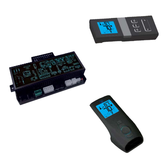
- Page 1 PROFLAME 2 Basic, Standard, Complete ADVANCED REMOTE CONTROL SYSTEMS...
- Page 2 The Proflame 2 is a modular remote control system that directs the functions of a hearth appliance. It was designed in Basic, Standard or Complete configurations for ATMO or FAN assisted appliances and now available in Basic ATMO, Complete ATMO or Complete FAN/ATMO versions.
- Page 3 BASIC PROFLAME 2 880 PROFLAME 885 PROFLAME Combination Gas Control Combination Gas Control STANDARD PROFLAME 2 OPTIONAL EXTERNAL RF RECEIVER LOCAL USER INTERFACE OPTIONAL PROFLAME TRANSMITTER 885 PROFLAME SPLIT FLOW Combination Gas Control COMPLETE PROFLAME 2 885 PROFLAME PROFLAME SPLIT FLOW LIGHT Combination Gas Control Transmitter...
-
Page 4: Main Characteristics
MAIN CHARACTERISTICS The table below shows the configurations currently available. PROFLAME 2 Feature Transmitter Icon TMFSLA TMFSL TMFL • • • Room Temperature Display • • • Child Lock • • • Low Battery indicator • • • On/Off Thermostat •... -
Page 5: System Components
SYSTEM COMPONENTS The BASIC System consists of four main elements: 1. Profl ame 2 Integrated Fireplace Control (IFC) Basic model 2. Profl ame 880, or 886 families of gas valves 3. Pilot assembly 4. Wiring harness to connect the IFC to the gas valve, pilot burner and control switches. The STANDARD System consists of seven main elements: 1. - Page 6 TRANSMITTER (Remote Control with LCD Display) The Proflame Transmitter uses a streamline design with a simple button layout and informative LCD display (Fig. 1). A Mode Key is provided to index between the features and a Thermostat Key is used to turn on/off or index through Thermostat functions (Fig. 1A & 1B & 2). Blue LCD display ON/OFF Key THERMOSTAT Key...
- Page 7 IFC MODULE The Profl ame 2 Integrated Fireplace Control (IFC) board is a device that allows the automatic ignition and pilot fl ame supervision, to command the functions of a hearth appliance, see fi g.3. It’s confi gured to control the ON/OFF main burner operation, giving the choice of both IPI (intermittent pilot ignition), and CPI (continuous pilot ignition) modes.
-
Page 8: Installation
INSTALLATION Proflame Wall Mount Transmitter The Proflame remote control is supplied with an adapter for wall mounting. Install the controller 1.5 m above floor level, well away from heat sources, kitchens, doors or windows. Metallic structures or radio interferences can reduce the operative distance of the device. Make sure to attach the adapter in a level plane without any distortion. - Page 9 IFC module The IFC can be placed inside a low temperature area of the appliance. Mounting into the appliance 1. Connect the wiring harnesses to the IFC. 2. Install the IFC in the appliance using the screws. (Fig. 4) 3. Insert the 4 AA type batteries in the battery holder with the correct polarity. 4.
- Page 10 The electrical connections must be in accordance to Fig. 5. ON / OFF IPI / CPI 0.190.XXX 0.880.XXX 0.886.XXX BATTERY 0.584.952 PACK 0.584.920 0.584.920 0.584.924 X5 X4 X3 X2 0.584.307 GROUND Chassis connection Fig. 5: Proflame 2 BASIC IFC & 880/886 PROFLAME wiring diagram.
- Page 11 Connecting to the 885 Gas Valve and IFC control board in STANDARD configuration (MFSLA) The electrical connections must be in accordance to Fig. 6. ON / OFF IPI / CPI 0.190.XXX 0.885.XXX 0.584.920 0.584.952 BATTERY 0.584.920 PACK 0.584.924 0.584.921 0.540.001 0.584.040 0.584.040 X9 X8...
- Page 12 Connecting to the 885 Gas Valve and IFC control board in COMPLETE configuration (FAN) The electrical connections must be in accordance to Fig. 8. ON / OFF IPI / CPI 0.190.XXX 0.885.XXX BATTERY 0.584.952 0.584.92x PACK (*) 0.584.921 0.540.001 0.584.040 0.584.040 X9 X8 X7 X6 X5...
- Page 13 OPERATING PROCEDURE FOR A BASIC CONTROL SYSTEM Before applying any power supply to the IFC board please verify that the electrical connections are in accordance to Fig. 5. Initializing the System for the first time Set the main burner ON/OFF command switch to the OFF position. If installed, set the pilot flame mode selector switch to the IPI position.
- Page 14 OPERATING PROCEDURE FOR A STANDARD OR COMPLETE CONTROL SYSTEM Before applying any power supplyto the IFC board, verify that the electrical connections are in accordance to either Fig. 6, 7, or 8. Initializing the System for the first time Install the 4 AA batteries into the battery bay. Note the polarity of the battery and insert into the battery holder as indicated on the Battery cover (+/-).
- Page 15 Turning OFF the Appliance With the system ON, press the ON/OFF Key on the Transmitter. The Transmitter LCD display will only show the room temperature (Fig. 8). At the same time the IFC will be commanded to turn off the burner. Depending on the system mode (IPI or CPI) the pilot may shut off (IPI) or remain lit (CPI) and the appliance burner turns OFF.
-
Page 16: Room Temperature
Room Thermostat ( Transmitter Operation) The Remote Control can operate as a room thermostat. The thermostat can be set to a desired temperature to control the comfort level in a room. To activate this function, press the Thermostat Key (Fig. 1). The LCD display on the Transmitter will change to show that the room thermostat is “ON”... - Page 17 Comfort Fan Speed Control (PROFLAME 2 MFSLA only) If the appliance is equipped with a hot air circulating fan, the speed of the fan can be controlled by the Proflame system. The fan speed can be adjusted through six (6) speeds. To activate this function use the Mode Key (fig.1) to index to the fan control icon (Fig.
- Page 18 Split Flow control The secondary burner is controlled by the split Flow. To activate this function use the Mode Key (fig. 1) to index to the SPLIT FLOW mode icon (fig. 18 & 19). Pressing the Up Arrow Key will activate the secondary burner. Pressing the Down Arrow Key will turn the secondary burner off.
- Page 19 Continous Pilot/Intermittent Pilot (CPI/IPI) selection With the system in "OFF" position press the Mode Key (fig. 1) to index to the CPI mode icon (fig. 22 & 23). Pressing the Up Arrow Key will activate the Continous Pilot Ignition mode (CPI). Pressing the Down Arrow Key will return to IPI.
- Page 20 Low Battery Power indicator Transmitter The life span of the remote control batteries depends on various factors: quality of the batteries used, the number of ignitions of the appliance, the number of changes to the room thermostat set point, etc. When the transmitter batteries are low, an Icon will appear on the LCD display of the transmitter (Fig.
-
Page 21: Dimensional Drawings
DIMENSIONAL DRAWINGS PROFLAME Transmitter Dimensions are in millimeters Ø3 Ø3 PROFLAME Wall Mount Transmitter Dimensions are in millimeters... - Page 22 DIMENSIONAL DRAWINGS 173.7 IFC Control Board Dimensions are in millimeters...
- Page 24 SIT S.p.A. Viale dell’Industria 31-33 35129 PADOVA - ITALY Tel. +39/049/829.31.11, Fax +39/049/807.00.93 www.sitgroup.it - e-mail: mkt@sitgroup.it...
Need help?
Do you have a question about the PROFLAME 2 Basic and is the answer not in the manual?
Questions and answers