Table of Contents
Advertisement
Quick Links
Advertisement
Table of Contents

Subscribe to Our Youtube Channel
Related Manuals for Cirrus Optimus+


Summary of Contents for Cirrus Optimus+
- Page 1 Instrument Handbook Optimus+ GPS Sound Level Meters...
- Page 2 Optimus+ Sound Level Meters – User Manual About this manual The instructions in this user manual refer to the operation of Cirrus Research plc Optimus sound level meters with version 5.0 or higher of the firmware. The instruments described in this manual are the Optimus+ Red (CR:160 series) and Optimus+ Green (CR:170 series) with GPS functionality.
- Page 3 You must not modify text, images or illustrations in any way. The material must be acknowledged as Cirrus Research plc copyright and you must give the title of the source document/publication. Where any third-party copyright material is identified you will need to obtain permission from the copyright holders concerned.
-
Page 4: Table Of Contents
Page 4 Optimus+ Sound Level Meters – User Manual Contents Introduction ............................5 First use ..............................7 Inserting the batteries ............................8 Setting the clock ..............................8 Calibration ................................9 Making a measurement ......................... 11 Operations in more detail........................12 NoiseTools ................................ -
Page 5: Introduction
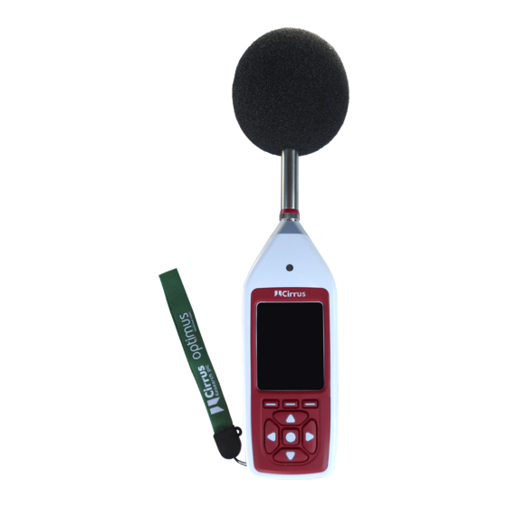
Optimus+ Sound Level Meters – User Manual Introduction Welcome to your Optimus+ GPS sound level meter. This next-generation instrument from Cirrus Research plc is powerful yet simple to use and is capable of a wide range of noise measurement functions. - Page 6 Page 6 Optimus+ Sound Level Meters – User Manual Battery cover screw Battery cover Tripod mount Power button...
-
Page 7: First Use
Page 7 Optimus+ Sound Level Meters – User Manual First use Your sound level meter has been shipped in reusable packaging that should be retained for safe shipment when returning the instrument for calibration or servicing. All Optimus+ GPS sound level meters come with the following standard accessories: •... -
Page 8: Inserting The Batteries
Page 8 Optimus+ Sound Level Meters – User Manual Inserting the batteries Your sound level meter is powered by 4 x AA alkaline batteries (also called MN1500 or LR6). We recommend that you use alkaline batteries to give the best performance. Remove the battery cover by loosening the captive locking screw (as shown in the diagram below). -
Page 9: Calibration
Page 9 Optimus+ Sound Level Meters – User Manual Please note that the clock might need to be set again if the instrument is stored without batteries for a prolonged period. Calibration All noise measuring instruments should be calibrated before each use because the microphone is susceptible to minor damage, even from small knocks. - Page 10 When calibration is complete, your instrument will display the level along with the correction or adjustment made. Your sound level meter is pre-set with the correction values needed for Cirrus Research microphone capsules, so no manual adjustment is required. The calibration level you should expect is 93.7 dB.
-
Page 11: Making A Measurement
Page 11 Optimus+ Sound Level Meters – User Manual Making a measurement Press the ‘start’ key to begin recording (on data logging instruments with the VoiceTag function switched on, the VoiceTag screen will show – press ‘skip’ to move on without recording a note). Your sound level meter is now measuring and recording noise data for all available functions, regardless of your selected view, and the red animated running icon will show in the top left of the information bar. -
Page 12: Operations In More Detail
Page 12 Optimus+ Sound Level Meters – User Manual Operations in more detail Please note: from this chapter on, the manual describes capabilities which are available on different models within the Optimus range. This includes the CR:16XX and CR:17XX GPS-enabled instruments. If you are unsure which capabilities your instrument has, you can check by looking at the general view/page 5 (and 6 on some models). -
Page 13: Connectors
Page 13 Optimus+ Sound Level Meters – User Manual The ambient light sensor on the front of the instrument will illuminate the keypad and adjust the brightness of the display automatically when the light level fails. If the pause function has been activated (described on page 18), the right soft key switches between pause and stop. -
Page 14: Screen Saver
Page 14 Optimus+ Sound Level Meters – User Manual External power via USB External power via multi-pin connector An AC output is available on the instrument via the 3.5 mm jack socket. The output is unweighted, and the output level can be adjusted using the options in the AC-out menu. This output can be used with external instrumentation. -
Page 15: Display
Page 15 Optimus+ Sound Level Meters – User Manual Display The instrument uses a high-resolution colour screen to show a clear and easy-to-read display of all the information you need. 4.5.1 Information bar The information bar shows icons when functions are active. Examples of the icons are shown in the diagram above. - Page 16 ‘bluescreen’ error message will show with an error code. If this should happen to your instrument, please make a note of the code so engineers at Cirrus Research can diagnose your problem accurately. After writing down the code, pressing the right key will clear the screen and the instrument can be used as normal.
-
Page 17: Audio Recording
(standard, high or studio). Details of the audio triggers can be found in Technical Note 28 - Audio Recording with the Optimus Green sound level meters. Please refer to the Cirrus Research plc website at www.cirrusresearch.co.uk/library/optimus. Pressing the audio key again stops the recording. There is no maximum duration of an audio recording set by default, but this can be changed in NoiseTools, and the parameters for the audio triggers can be configured in NoiseTools. -
Page 18: Timers
Page 18 Optimus+ Sound Level Meters – User Manual Timers The single and repeat timers allow you to make precisely timed measurements over pre-set or custom defined durations, which are set on the instrument using the storage options menu (see next chapter). -
Page 19: Memory
Page 19 Optimus+ Sound Level Meters – User Manual An example of this would be if, during the measurement of cars on a road, a large truck passed by the measurement location. If the intention was only to measure cars, the truck can be excluded from the overall measurement data by pressing the ‘pause’... -
Page 20: 4.12 Bluetooth
Page 20 Optimus+ Sound Level Meters – User Manual 4.12 Bluetooth The instrument can be connected to a Bluetooth low-energy mobile device to allow control, live view and overall measurement download. To connect to a device, download the dBactive application from your smartphone’s app store. On the instrument, go to the ‘Advanced Options’ menu and select the ‘Bluetooth’... - Page 21 Page 21 Optimus+ Sound Level Meters – User Manual 4.13.1 GPS AssistNow Data NoiseTools automatically downloads GPS AssistNow data to instruments configured to use the GPS Module. This is used to reduce the time to first fix (TTFF). Typically, the use of GPS AssistNow will reduce TTFF from up to five minutes, to under 60 seconds.
- Page 22 Page 22 Optimus+ Sound Level Meters – User Manual A pin identifies the measurement location.
- Page 23 Page 23 Optimus+ Sound Level Meters – User Manual View coordinate data by clicking the ‘Detail’ tab. Coordinate and map data will also be visible within NoiseTools reports. 4.13.5 GPS Data on Your Instrument Navigate to the General View screen and scroll down to page 3.
- Page 24 Page 24 Optimus+ Sound Level Meters – User Manual When GPS is enabled, a grey satellite icon will be displayed at the top of the instrument’s screen. When a GPS signal is acquired, the satellite icon will change to green and coordinate data will be displayed.
-
Page 25: Getting To Know Your Instrument - Features & Capabilities
Page 25 Optimus+ Sound Level Meters – User Manual Getting to know your instrument - features & capabilities Optimus+ GPS sound level meters are designed around a modular structure that allows an instrument to be upgraded and updated with new capabilities (functions), protecting your investment for the future. - Page 26 When a tone is detected, the band is highlighted in blue on both the graphical and numerical pages. The tone detection method can be set to either the Cirrus improved method (default setting) or the ISO 1996 method in NoiseTools.
- Page 27 For more information, please see Technical Note 32 – Tonal noise detection with Optimus sound level meters, available download from Cirrus Research website www.cirrusresearch.co.uk/library/optimus/. 5.1.7 Ln view The Ln view shows the statistical Ln values calculated during the measurement. The first seven Ln values are set by default to commonly used values, and 8-14 are definable in NoiseTools.
-
Page 28: High-Level Noise Measurement
Page 28 Optimus+ Sound Level Meters – User Manual The displayed values will differ depending upon the language selection chosen for the instrument. 5.1.11 Vehicle noise view The vehicle noise view and optional wired remote is designed to meet the requirements of ISO 5130-1982 &... -
Page 29: Menus
Page 29 Optimus+ Sound Level Meters – User Manual Menus In the following menus, different options can be chosen on the instrument. To activate a function, press the ‘mark’ soft key to put a tick in the square box. You can now use the up and down soft arrow keys to select your setting and use the ‘OK’ soft key to confirm it. - Page 30 Page 30 Optimus+ Sound Level Meters – User Manual Restore factory settings Restores the instrument back to its original factory setup. AC out On/off +20 dB Gain High levels (70-140 dB) or low levels (20-90 dB) Audio quality Standard quality (16-bit, 16 kHz) High quality (24-bit, 48 kHz) Studio quality (32-bit, 96 kHz) Audio triggers...
- Page 31 Page 31 Optimus+ Sound Level Meters – User Manual Language English, Français, Deutsch, Español, Italiano Please note: when changing language, the instrument must be restarted for the change to take effect. 6.1.7 Storage options Time history rate 2s, 1s (default), ½s (500 ms), ¼s (250 ms), 1/8s (125 ms), 1/10s (100ms), 1/16s (62.5ms), 1/100s (10ms) Selected rate applies to all measurements including octaves.
-
Page 32: Additional Information
Page 32 Optimus+ Sound Level Meters – User Manual Additional information Additional information on the following topics can be downloaded from the Cirrus Research website. Please visit www.cirrusresearch.co.uk/library/optimus/ for the latest versions of these documents. Technical Note 28 - Recording audio with the Optimus Green (CR:170) sound level meters... -
Page 33: Appendices
IEC 61672 test data Technical data for IEC 61672 testing is contained in the Part B document, which can be downloaded from the Cirrus Research plc website. This chapter of the manual contains the overall specifications for the Optimus Yellow (CR:150), Optimus Red (CR:160), Optimus Green (CR:170) and Optimus Purple (CR:190) sound level meters. - Page 34 Page 34 Optimus+ Sound Level Meters – User Manual Specifications Microphone Class 1 instruments: MK:224 or MK:229 pre- polarized free-field 1/2” Condenser Class 2 instruments: MK:216 pre-polarized free- field 1/2” condenser Microphone preamplifier MV:200 removable preamplifier for Class 1 & Class 2 instruments Measurement range A single measurement range covering 120 dB...
- Page 35 Page 35 Optimus+ Sound Level Meters – User Manual Specifications Start Time, Duration, LAFMax, LAeq, LCPeak, L10, L90, Overload, Calibration data, Diagnostic information. VoiceTag audio recording User selectable recording of voice notes before each measurement for download to NoiseTools software (data logging versions) 30 seconds per recording with audio files downloaded with noise measurement information.
-
Page 36: Views
Page 36 Optimus+ Sound Level Meters – User Manual Views 8.3.1 Sound level view Sound level: Lxy where x = A, C, Z ; y = F, S, I Maximum sound level: LxyMax where x = A, C, Z ; y = F, S, I Minimum sound level: LxyMin where x = A, C, Z ;... - Page 37 Page 37 Optimus+ Sound Level Meters – User Manual L5.0 L10.0 L50.0 L90.0 L95.0 L99.0 Lns 7-14 are user defined, turned off by default. Ln values are calculated using 1/16 second LAF samples by default. Sampling rate, time weighting and frequency weighting can be changed in NoiseTools. Instruments with the “statistical levels x 2”...
- Page 38 Page 38 Optimus+ Sound Level Meters – User Manual Indicated in white where LAeq,60min ≤ 100 dB LAeq,60min max LAeq,60min max date and time Page 3 LASMax LASMax date and time 8.3.8 Environmental view All language selections other than German: Page 1 LAeq LAymax *...
-
Page 39: Stored Measurements
Page 39 Optimus+ Sound Level Meters – User Manual Graphical display of cumulative Leq for each 1:1 octave band Page 3 (Displayed when the instrument is measuring) Graphical display of cumulative Leq for each 1:3 octave band Page 4 Graphical display Lf real time 1:1 octave bands with the highest value for each band (updated every 1/16 second) Page 5 (Displayed when the instrument is measuring) Graphical display Lf real time 1:3 octave bands with the highest value for each band... - Page 40 Page 40 Optimus+ Sound Level Meters – User Manual 8.4.3 Dose view Overall: Leq2, Leq3. (Lavg stored, TWA, % dose & est % dose also available) Time history: Leq2, Leq3 Time history data rate is user configurable in the global settings Measurement run time Time &...
- Page 41 Page 41 Optimus+ Sound Level Meters – User Manual Page 3 LASMax LASMax date and time On instruments with firmware version below 2.8: Page 1 LASMax LA95 Page 2 LASMax LA95 8.4.8 Menu/quick settings The quick settings available are: UK: 3 dB, no threshold, no time weighting, criterion level of 85 dB EU: 3 dB, no threshold, no time weighting, criterion level of 85 dB OSHA HC &...
-
Page 42: Electrical Outputs
The DC output is available using a ZL:174 output cable. This cable is available from Cirrus Research plc or your local distributor. Do not use any other cable with the Optimus+ GPS. This may damage the instrument and invalidate your warranty. - Page 43 Page 43 Optimus+ Sound Level Meters – User Manual 8.5.3 Threshold triggered output An external discrete available on the 18 Pin Multi-IO socket at the bottom of the instrument can be triggered when an audio trigger event is detected. This trigger will toggle the output from 0 to 3.3V and can be used to trigger external devices, for example a camera or noise warning sign.
-
Page 44: Acoustic Calibrator Information
Optimus+ Sound Level Meters – User Manual Acoustic calibrator information This chapter refers to the use of a Cirrus Research plc CR:514 or CR:515 acoustic calibrator. Setting up the calibrator Press the power button on the end of the calibrator to switch the unit on. The indicator will illuminate to show that the unit is operating. -
Page 45: Changing The Battery
Page 45 Optimus+ Sound Level Meters – User Manual Your Optimus+ GPS sound level meter will automatically make adjustments for the level produced by the acoustic calibrator and the microphone type fitted to the instrument. 9.2.1 Background noise In order for the calibrator to operate as intended, the ambient acoustic noise level should be no greater than 80 dB(A). -
Page 46: Specifications
‘zero degrees’ or ‘head-on’ incidence, and the pressure level generated by the calibrator. The correction is typically -0.3 dB for Cirrus ½ inch microphones (making the effective calibration level 93.7dB). - Page 47 Page 47 Optimus+ Sound Level Meters – User Manual An example of the procedure used to calculate the value for an MK:224, MK:229 or MK:216 microphone is shown below: Level = 94.0 dB + microphone correction Level = 94.0 dB + ( -0.3 dB) Level = 93.7 dB...
-
Page 48: Eu Declaration Of Conformity
Page 48 Optimus+ Sound Level Meters – User Manual EU Declaration of Conformity Manufacturer: Cirrus Research plc Acoustic House Bridlington Road North Yorkshire YO14 0PH United Kingdom Equipment description. The following equipment manufactured after 1st January 2018: CR:151 Sound Level Meter (A & B Versions) CR:152 Sound Level Meter (A &... -
Page 49: Product Guarantee And Extended Warranty
This two-year period covers failure and poor workmanship only. 2. If the product is calibrated by Cirrus Research or an authorised calibration and service centre, then the initial 12-month warranty is extended by a further 12 months, with the same conditions, for up to 15 years in total. - Page 53 www.cirrusresearch.com sales@cirrusresearch.com...
Need help?
Do you have a question about the Optimus+ and is the answer not in the manual?
Questions and answers