Table of Contents
Advertisement
Quick Links
Advertisement
Table of Contents

Related Manuals for Accorroni RPE 019

Summary of Contents for Accorroni RPE 019
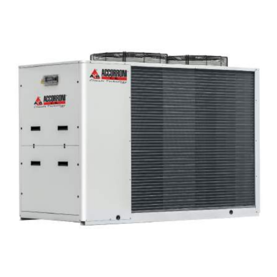
- Page 1 Chillers and heat pumps RPE 19÷44 - HPE 18÷40...
- Page 2 ORIGINAL INSTRUCTIONS The water chillers and heat pumps comply with directive 2014/68//EC (PED).
- Page 3 SERIES Water chillers and heat pumps of the series MPE are designed performance with relatively low energy consumption and fea- for outdoor installation in both residential and commercial tures 18 models in the chiller versionand 25 in heat pump veri- applications.
-
Page 4: Constructive Features
CONSTRUCTIVE FEATURES STRUCTURE Galvanised sheet steel structure treated with a polyester powder The compressor compartment is completely sealed and may be coating (Ral9002) suitable for outdoor applications, for an at- accessed on 3 sides thanks to easy-to-remove panels that greatly tractive look and effective resistance to corrosive agents. - Page 5 Ū Cycle reversing valve (MPE H) Ū Complete alarm management. Ū Dynamic control of the setpoint according to the outdoor Ū Water circulation pump air temperature. Ū antifreeze heating element (optional) Ū Can be connected to an RS485 serial line for supervisory / Ū...
-
Page 6: Configuration Options
CONFIGURATION OPTIONS The MPE series consists of 18 models in cooling only version and R410a refrigerant. 25 in reversible heat pump version. all models operates with » Configuration options 1 Basic Expansion valve 2 Advanced 0 Mechanical 3 Advanced + GSM modem board A Electronic 4 Advanced + clock card Water pump and accessories... - Page 7 4 DIMENSIONS » HPE 28 - 40 DESCRIPTION R410A-air heat-exchanger 11 Water safety valve 12 Liquid receiver (fan housing)(MPE H) R410A-water heat-exchanger 13 Circulation pump Fans 14 Compressor Water differential pressure switch (fan housing) 15 Refrigerant filter Automatic air purge valve 16 Low pressure switch and charge port Expansion vessel (fan housing) 17 High pressure switch and charge port...
- Page 8 » RPE HPE 18 - 27 1588 1565 150.5 1112 241.5 1,5 m 1,5 m LEGENDA Ingresso acqua 1" 1/4 femmina Uscita acqua 1" 1/4 femmina Scarico valvola di sicurezza con portagomma Alimentazione acqua 1/2" maschio (rubinetto optional) Scarico acqua 1/2" femmina Alimentazione elettrica Ø...
- Page 9 » RPE HPE 28 - 40 ; 1987.5 303.7 729.8 623.8 303.7 379.5 1965 1,5 m 1,5 m LEGENDA Ingresso acqua 1" 1/4 femmina Uscita acqua 1" 1/4 femmina Scarico valvola di sicurezza con portagomma Alimentazione acqua 1/2" maschio (rubinetto optional) Scarico acqua 1/2"...
-
Page 10: Technical Features
TECHNICAL FEATURES RPE WATER CHILLERS RATED TECHNICAL DATA » RPE water chillers rated technical data Power supply V-ph-Hz 400 - 3 - 50 Cooling capacity (1)(E) 19,70 22,50 26,40 Total power input (1)(E) 6,61 7,53 9,50 Absorbed rated current 13,11 14,68 16,67 (1)(E) - Page 11 » RPE water chillers rated technical data Power supply V-ph-Hz 400 - 3 - 50 Cooling capacity (1)(E) 27,90 31,20 34,80 39,40 Total power input (1)(E) 8,91 10,40 11,70 13,10 Absorbed rated current 16,36 18,59 20,92 22,94 (1)(E) 3,13 3,00 2,97 3,01 SEER...
- Page 12 » HPE heat pumps rated technical data Power supply V-ph-Hz 400 - 3 - 50 Cooling capacity (1)(E) 16,70 19,00 23,10 27,30 Total power input (1)(E) 6,40 7,31 8,19 8,81 Absorbed rated current 11,87 13,11 14,68 16,36 (1)(E) 2,61 2,60 2,82 3,10 SEER...
- Page 13 » HPE heat pumps rated technical data Power supply V-ph-Hz 400 - 3 - 50 400 - 3 - 50 400 - 3 - 50 Cooling capacity (1)(E) 30,60 34,10 38,60 Total power input (1)(E) 10,20 11,60 13,10 Absorbed rated current 18,59 20,92 22,94...
-
Page 14: Calculation Factors
CALCULATION FACTORS CHANGE IN OPERATING PARAMETERS WITH DT OTHER THAN 5°C after identifying the unit’s performance in the terms of the desired outlet water temperature, correct the value by multiplying it by the following corrective coefficients. Difference between water inlet Corrective coefficient of cooling/ Correction coefficient of Correction coefficient of water... -
Page 15: Sound Levels
SOUND LEVELS » Sound levels RPE Sound power level, low- 125 Hz (1) 250 Hz (1) 500 Hz (1) 1000 Hz (1) 2000 Hz (1) 4000 Hz (1) 8000 Hz (1) LwA (2) noise version dB(A) dB(A) 76,6 70,3 69,7 65,6 58,4 53,4... -
Page 16: Operating Limits
OPERATING LIMITS The graphs below illustrate the operating limits of MPE units (in the case of continuous operation) in relation to the outlet water temperature and outdoor air temperature. Operating limits Water chiller Heat pump Inlet air temperature (°C) Outlet water temperature (°C) Temperature difference on the water side (°C) Outdoor air temperature (°C) 1. -
Page 17: Operating Limits In Chiller Mode
OPERATING LIMITS IN CHILLER MODE » Operating limits in chiller mode opz 1+2 opz 2 opz 1 opz 1 + EEV opz 1+2 opz 1+2 Tbs1 Outdoor temperature (dry bulb) Outlet water temperature OPZ 1 Condensing control OPZ 2 Glycol + low temperature option OPZ 1+2 Condensation control + glycol + low temperature option Electronic expansion valve Standard... -
Page 18: Operating Limits In Heat Pump Mode
OPERATING LIMITS IN HEAT PUMP MODE » Operating limits in heat pump mode EEV+CC F08=10 F09=2 F03=20 GAIN 5 int time 100 Ta (°C) Relative humidity of outdoor air Tbs1 Outdoor temperature (dry bulb) Outlet water temperature Operating range calculated with temperature difference of 5°C on the water side. Extended operating envelope in heat pump mode heat pump operation within the right area of the extended operating envelope (beyond standard limits) can be allowed only for units equipped with condensation control (or EC fans) and electronic expansion valve... - Page 19 » MPE T76 10.2 Y FILTER PRESSURE DROPS The table below shows the pressure drops of the Y filter (Δp) as a function of the water flow rate (Qw), assuming an average water temperature of 10 °C, » MPE H 004 - 008 RG66004288-09 all copying, even partial, of this manual is strictly forbidden...
-
Page 20: Water Circuit
12 WATER CIRCUIT When setting up the water circuit of the unit, it is advisable to follow the directions below and in any case comply with local or na- tional regulations. Connect the pipes to the chiller using flexible couplings to prevent the transmission of vibrations and to compensate thermal expansions. - Page 21 Height difference of system Models Charging pressure of expansion tank Maximum system water content RPE19 - 027 ; HPE 018 - 024 <13 HPE 28 - 40...
- Page 22 12.2 WATER CIRCUIT » MPE ( evaporator and pump) Only for MPE C 28-40; T30-T44; T54-T76 MPE H 28-66; T30-T45; T54-T76 LEGEND 12 Clapet valve Evaporator 13 - 14 - 15 Differential pressure switch Air purge valve 16 - Pressure gauge 17 - Drain 18 -...
- Page 23 » RPE HPE (evaporator) LEGEND Evaporator Security valve 10 Antifreeze electric heating 11 - 12 - Air purge valve Pressure gauge 13 Differential pressure switch Drain ------ Internal and external borderline ——— OPTIONAL » RPE HPE (evaporator and tank) LEGEND Evaporator Buffer tank Expansion vessel...
- Page 24 » RPE HPE (evaporator, pump and tank) Only for MPE C 09-27 MPE H 10-27 NOT for MPE H 04-08 Only for MPE C 28-40; T30-T44; T54-T76 MPE H 28-66; T30-T45; T54-T76 LEGEND 12 Clapet valve Evaporator 13 - 14 - 15 Differential pressure switch Air purge valve Pressure gauge...
- Page 25 12.3 DESUPERHEATER 12.3.1 Recommended water circuit The partial heat recovery option is provided by a braze-welded plate heat exchanger placed in series on the compressor delivery (typically in series in relation to the finned pack condenser). Its size is designed to limit pressure drops on the refrigerant side to a minimum.
- Page 26 12.3.2 Water pressure drop » Water pressure drop desuperheater 54-66 HPE 020-T45 019 - T45 004-019 009-019 HPE 54-T76 1000 2000 3000 4000 5000 6000 7000 Qw (l/h) 12.3.3 Heating capacities corrective factors » De-Superheather heating capacities corrective factors Air temperature (K) Inlet water temperature / Outlet water temperature 40/50 50/55...
-
Page 27: Installation Clearance Requirements
13 INSTALLATION CLEARANCE REQUIREMENTS To guarantee the proper functioning of the unit and access for to minimise noise and vibrations transmitted to the ground. maintenance purposes, it is necessary to comply with the Ū Even greater insulation may be obtained, however, by using mini-mum installation clearance requirements shown in figures vibration damping base supports (available as optional ac- installation space rpe 18 - 27 , installation space hpe 28-40 -. - Page 28 » RPE 18 - 27 RG66004288-09 all copying, even partial, of this manual is strictly forbidden...
- Page 29 » RPE HPE 28 - 40...
- Page 30 14 SITING AND DAMPERS It is important to bear in mind the following aspects when with physical, sensorial or mental problems, inexpert or unpre- choosing the best site for installing the unit: pared, without supervision. Be careful that children do not ap- Ū...
-
Page 31: Electrical Data
16 ELECTRICAL DATA 16.1 ELECTRICAL CONNECTIONS (see the electric control board layout supplied with the unit all operations must be performed by qualified service personnel ), marked in accordance with current laws and regulations. For any electri- cal work on the unit, refer to the electric diagrams supplied with If you wish to include: the unit. - Page 32 16.2 ELECTRICAL DATA » RPE HPE RPE HPE Maximum power input 13,60 14,50 18,00 18,30 18,90 21,80 Maximum current absorption Star up current Startup current with soft starter Fan motor rated power 0,14 0,14 0,14 0,32 0,32 0,32 Fan motor rated current 0,64 0,64 0,64...
- Page 33 » HPE Maximum power input 12,50 13,60 14,50 18,30 18,90 21,80 22,40 Maximum current absorption Star up current Startup current with soft starter Fan motor rated power 0,14 0,14 0,14 0,32 0,32 0,32 0,32 Fan motor rated current 0,64 0,64 0,64 1,75 1,75...
- Page 34 » Main electrical connection of units » PCD remote control panel electrical connection diagram » PCDS remote control panel electrical connection diagram S T N P 3+N 50 NOTE: On the terminal block of the electric control panel a voltage of 24V will be present at the 50/24V terminals in the event of an alarm;...
- Page 35 A2B Accorroni E.G. s.r.l. Via d’Ancona, 37 - 60027 Osimo (An) - Tel. 071.723991 web site: www.accorroni.it - e-mail: a2b@accorroni.it...
Need help?
Do you have a question about the RPE 019 and is the answer not in the manual?
Questions and answers