Sign In
Upload
Download
Table of Contents
Contents
Add to my manuals
Delete from my manuals
Share
URL of this page:
HTML Link:
Bookmark this page
Add
Manual will be automatically added to "My Manuals"
Print this page
×
Bookmark added
×
Added to my manuals
Manuals
Brands
Panasonic Manuals
Digital Camera
Lumix DC-GH5SP
Service manual
Panasonic Lumix DC-GH5SP Service Manual
Digital camera/body
Hide thumbs
1
Table Of Contents
2
3
4
5
6
7
8
9
10
11
12
13
14
15
16
17
18
19
20
21
22
23
24
25
26
27
28
29
30
31
32
33
34
35
36
37
38
39
40
41
42
43
44
45
46
47
48
49
50
51
52
53
54
55
56
57
58
59
60
61
62
63
64
65
66
67
68
69
70
71
page
of
71
Go
/
71
Contents
Table of Contents
Troubleshooting
Bookmarks
Table of Contents
Table of Contents
1 Safety Precautions
General Guidelines
Leakage Current Cold Check
Leakage Current Hot Check (See Figure. 1)
2 Warning
Prevention of Electrostatic Discharge (ESD) to Electrostatically Sensitive (ES) Devices
How to Recycle the Lithium Ion Battery (U.S. Only)
How to Replace the Lithium Battery
3 Service Navigation
Introduction
Important Notice
Service Notes
General Description about Lead Free Solder (Pbf)
How to Define the Model Suffix (NTSC or PAL Model)
4 Specifications
Camera Body
5 Location of Controls and Components
Camera Body
6 Service Mode
Error Code Memory Function
7 Troubleshooting Guide
Checking Method of Body
Wi-Fi Circuit (Wi-Fi BT P.C.B.)
8 Service Fixture & Tools
Service Fixture and Tools
Clean Box
When Replacing the Main P.C.B
Service Position (When Checking the each P.C.B.)
9 Disassembly and Assembly Instructions
Camera Body Part
10 Measurements and Adjustments
Matrix Chart for Replaced Part and Necessary Adjustment
11 Maintenance
Notice in External Cleaning
12 Block Diagram
Overall Block Diagram
System Control (1) Block Diagram
System Control (2) Block Diagram
Video/Audio Process (1) Block Diagram
Video/Audio Process (2) Block Diagram
Video/Audio Process (3) Block Diagram
Video/Audio Process (4) Block Diagram
Hot Shoe Block Diagram
Flash Syncro & LTC Block Diagram
Lens Block Diagram
Power (1) Block Diagram
Power (2) Block Diagram
Power (3) Block Diagram
Power (4) Block Diagram
13 Wiring Connection Diagram
Interconnection Diagram
14 Schematic Diagram
15 Printed Circuit Board
16 Exploded View and Replacement Parts List
Advertisement
Quick Links
1
Service Mode
2
Disassembly and Assembly Instructions
3
Exploded View and Replacement Parts List
4
Schematic Diagram
5
Printed Circuit Board
Download this manual
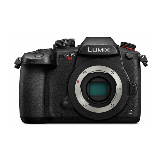
Digital Camera/Body
DC-GH5SP
Model No.
DC-GH5SPP
DC-GH5SE
DC-GH5SEE
DC-GH5SGA
DC-GH5SGC
DC-GH5SGD
DC-GH5SGH
DC-GH5SGK
DC-GH5SGN
DC-GH5SGT
DC-GH5SGW
Colour
Black Type
© Panasonic Corporation 2018 Unauthorized copy-
ing and distribution is a violation of law.
ORDER NO. DSC1801002CE
B26
Table of
Contents
Previous
Page
Next
Page
1
2
3
4
5
Advertisement
Table of Contents
Need help?
Do you have a question about the Lumix DC-GH5SP and is the answer not in the manual?
Ask a question
Questions and answers
Related Manuals for Panasonic Lumix DC-GH5SP
Digital Camera Panasonic Lumix DC-GH5S Operating Instructions For Advanced Features
(372 pages)
Digital Camera Panasonic LUMIX DC-GH5S Owner's Manual
(132 pages)
Digital Camera Panasonic DC-GH5S Quick Manual
4k photo (2 pages)
Digital Camera Panasonic DCGH5SGNK Basic Operating Instructions Manual
(128 pages)
Digital Camera Panasonic LUMIX DC-GH5S Operating Instructions For Advanced Features
(385 pages)
Digital Camera Panasonic Lumix DC-GH5SE Service Manual
Digital camera/body (71 pages)
Digital Camera Panasonic DC-GH5 Basic Owner's Manual
Lens kit/body (128 pages)
Digital Camera Panasonic LUMIX DC-GH5L Basic Operating Instructions Manual
(124 pages)
Digital Camera Panasonic Lumix DC-GH5EFK Owner's Manual For Advanced Features
(347 pages)
Digital Camera Panasonic DC-GH5 Owner's Manual
(347 pages)
Digital Camera Panasonic LUMIX DC-GH5PRO Operating Instructions For Advanced Features
(380 pages)
Digital Camera Panasonic Lumix DC-GH5M2 Quick Start Manual
(228 pages)
Digital Camera Panasonic LUMIX DC-GH5M2 Owner's Manual
(140 pages)
Digital Camera Panasonic LUMIX DC-GH5M2 Owner's Manual
(96 pages)
Digital Camera Panasonic LUMIX DC-GH5M2 Operating Instructions Manual
(813 pages)
Digital Camera Panasonic Lumix GH5 II Settings Manual
(24 pages)
This manual is also suitable for:
Lumix dc-gh5spp
Lumix dc-gh5se
Lumix dc-gh5see
Lumix dc-gh5sga
Lumix dc-gh5sgc
Lumix dc-gh5sgd
...
Show all
Lumix dc-gh5sgh
Lumix dc-gh5sgk
Lumix dc-gh5sgn
Lumix dc-gh5sgt
Lumix dc-gh5sgw
Table of Contents
Print
Rename the bookmark
Delete bookmark?
Delete from my manuals?
Login
Sign In
OR
Sign in with Facebook
Sign in with Google
Upload manual
Upload from disk
Upload from URL


Need help?
Do you have a question about the Lumix DC-GH5SP and is the answer not in the manual?
Questions and answers