Table of Contents
Advertisement
Quick Links
Advertisement
Table of Contents

Related Manuals for Digifly FMS50MM


Summary of Contents for Digifly FMS50MM
- Page 1 FMS50MM + EFIS FMS50MM EFIS Instrumentation FMSAT ver 4.10 uk 16 / 01 / 2002...
- Page 2 - damage is caused by accidents including but not limited to lightning, water or fire, misuse or neglect. In case your Digifly product is not working correctly or is defective, please contact your Digifly dealer. In order to avoid unnecessary inconvenience, we advise you to read the operating instructions carefully before contacting your Dealer.
-
Page 3: Table Of Contents
INDICE Introdutcion INSTALLATION 1.1 FMS50MM ......... Pag. 1.2 FmmAT sensor installation ..Pag. 1.2.1 Warnings ....Pag. 1.2.2 Mounting ....Pag. 1.2.3 Air pressure sensing . Pag. 1.2.4 Electrical supply ..Pag. 1.2.5 Connection of interface cable ..Pag. 1.2.6 Operative lmits ..Pag. - Page 4 4.6 Back light / Map colors ....Pag. NOTES about Moving Map Pag. 22,23,24 EFIS MODULE 5.1 Introcuction ........ Pag. 5.2 Overview ........Pag. 5.2.1 Description of individual instruments ....... Pag. 5.3 Description of fmsAT ....Pag. 5.4 Meaning of keys with EFIS ..Pag. 5.5 Altimeters / Anemometers adjust.
- Page 5 Introduction The Digifly instrumentation is a full modular system which, depend on the different modules, let you able toobtaindifferent functions: Moving-MapGPSor Moving-Map GPS + EFIS. Moving-Map Gps + Efis Necessary modules for the full functions GPS-Moving-MAp + Efis : Moving-Map Gps...
-
Page 6: Installation
Installation FMS50MM - The unit should be connected to the battery through a dedicated switch and fuse. - Usemetal only spark plug caps. - Never fasten sensor cables to high voltage spark plugs cables or lay down near high voltage coils. -
Page 7: Mounting
The Red (positive) and Black (negative) wires out of the female plug to fms50 (provided in the installation kit) should be connected to the same electrical supply of FMS50MM, to switch on simultaneously both units. 1.2.5 Connection of interface cable fmsAT Allow easy accessibility since the same cable is used for downloading to FMS50MM of the software upgrades. -
Page 8: Electrical Schemes
1.3 Electrical Schemes fms50 (back view) PITOT TUBE RCA PLUG AUTOPILOT STATIC INPUT RX GPS NMEA TX AUTOPILOT NMEA GPS & I/O RECEIVER +12V max 150 mA LED Warning YELLOW 470Ω ½W ORANGE POWER 470Ω ½W LED Alarm BLACK fms at (back view) 9 poles male 9 poles female STATIC... -
Page 9: Calibration And Configuration
2 Calibration and configuration Calibration of fmsAT 2.1.1 Calibration notes Following this procedure magnetic field sensors and acceleration sensors are calibrated on site. No re-calibration is needed, unless other instruments are added in the vicinity of the fmsAT, or if the unit is installed into another instrument panel. -
Page 10: Autoconfiguration Of
Scroll with key to CALIB_LOCAL_Y and press key twice. With keys enter a compensation so that the value under FINAL r e a d s 1800. Store the value pressing key. (Attention! This is the Z axis component of the magnetic field depends on latitude and longitude. Consult the table in the appendix for the value in your area). -
Page 11: Switching On And Off Pag
3 Switching on and off First turn on the airplane engine and then power up FMS50 with connected modules(fmsAT). To switch off select the main MENU page and select the function POWER OFF. The message WAIT FEW SECONDS will appear, followed by SWITCH OFF THE UNIT. FmsAT does not need a switch on/switch off sequence. -
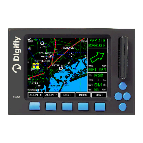
Page 12: Moving Map
Moving Map 4.1 Moving map screen The moving map screen is divided in 2 sections: - Navigation data section ( , , ). ’ “ ” - Cartographic section ( ). • 4.1.1 Nagigation data Bottom section ’ Name of destination if active ( Time to destination ( Distance to Destination ( Ground Speed (... - Page 13 4.1.2 Cartographic section • In this section of the screen the electronic map is presented North UP with details depending on scale and type ofC-MAP cartridge inserted. The cursor position is indicated on the screen by a cross( ). Aircraft position ( ) with the indication of the Course Prediction (continuous blinking red line).
-
Page 14: Navigation Data
FIX/DEST Cursor moves to actual position or to selected destination. MENU To access to all system functions. LIGHT (FMS50MM) Sets back-light intensity. MOVE CURSOR Use round Up/ Down/ Left/ Right to mov the cursor. INSTRUMENTATION EFIS / FMS50MMI Selects Instrumentation page. -
Page 15: Menues
altimeter settings or current coordinates. Keyboard’s main functions summary Key Function Function Zoom in. Info airports. Œ ŒŒ Zoom out. Info controlled areas. • •• Fix/Destination. Go to waypoint (on/off). Ž ŽŽ MainMenu All screen (on/off). • •• Light or Instrument. Altimeter (on/off). -
Page 16: Save Fix
The following functions are supported: UP/DOWN ENTER A NEWWAYPOINT : Press keys to select line 1 (empty line), press EDIT and enter using UP/ DOWN/ LEFT/ RIGHT waypoint data. SAVE confirms, deletes. MODIFY WAYPOINT DATA Select waypoint with UP/ DOWN keys, then press EDIT... -
Page 17: Routes
4.3.3 Routes A route is defined as a waypoint list to be reached in sequence. Beginning from first waypoint the program will indicate the direction (note ADF indicator) to reach the next waypoint.Whenthesubsequent wayoint is reached the next waypoint in the list will be automatically activated. - Page 18 Meaning of keys in edit Route UP/ DOWN/ LEFT/ RIGHT you can move between waypoints or select the first empty position to enter a new waypoint. INSERT key Inserts a waypoint in the current position. Pressing INSERT the waypoint data base is opened, the waypoint can be selected (edit functions also available).
- Page 19 2 - Double click on a waypoint which belongs to a route. If a waypoint belongs to more than one route, the route with the lowest number will be selected. If you have already a waypoint active you should first deactivate it with a double click then you can select the route...
-
Page 20: Settings
Deactivating a route Two modes are foreseen From the main menu enter in the ROUTES menu, select the active route and press DEACT. Double click on the FIX key with a cursor in any position of the screen, different from the waypoints belonging to the Active Route. Deleting a route Enter in the ROUTES menu select the Route to be deleted and press CLEAR. -
Page 21: Gps Page
MARINE elements AIDS. Navigational markers and beacons. COAST. RESTR. Restrictions. DEPTH. UNITS settings DIST (Nm, Sm, Km). ALT. (Ft, m) SPEED (Knt, Km/h) TRACK Settings Valid fixes leave a dot on screen which remain also after power off. TRK RATE Time between dots. -
Page 22: Dead Reckoning
4.4 Dead Reckoning This function is automatically entered if the GPS sensor does suspends transmission of valid fixes. New estimated positions are calculated from previous valid speed and direction data. Coordinates will blink and change color to red and every 5 seconds a beep will sound. After 2 minutes of continuous lack of GPS signal Dead Reckoning is disabled and no navigation data will be presented and 3 consecutive beeps will sound. - Page 23 NOTES...
- Page 24 NOTES...
- Page 25 NOTES...
-
Page 26: Introcuction
EFIS Instrumentation 5.1 Introduction Digifly EFIS consists of a single screen page with all flight and attitude parameters. It adds to the well known Moving Map display FMS50MM the following new instrument functions: Roll, Pitch, compass, Skid, turn-indicator, G-Meter, 3 altimeters, Anemometer, Variometer. -
Page 27: Description Of Individual Instruments
5.2 Overiview The EFIS instrumentation is composed by: - Altimeter ref. Pressure - ADF-GPS arrow - Skid indicator - Time of turn - Pitch and roll indicator - Variometer - Altimeters - Anemometer - Compass - G-meter 5.2.1 Description of individual instruments Barometric Altimeter: QNE, QFE, QNH are shown, all depend from the absolute pressure sensor of the fmsAT module. -
Page 28: Description Of Fmsat
Vario: Range +- 5 m/s or higher, sensitivity 0.2 m/s. Anemometer: (Indicated Air Speed IAS) Automatically zeroed at power-up of fmsAT, with an operating range berween 20 to 400 Km/h, accuracy between 100 to 400 Km/h 1 Km/h. Compass: Moving scale presentation with resolution of 1°. Accuracy depends on calibration (see calibration procedure) and with the airplane at constant speed and direction can reach 1°. -
Page 29: Zero Qfe
Altimeters adjustment (EFIS) 5.5.1 Zero QFE To zero QFE press ALTIM key to select QFE, then push the PRESS key (the field becomes red), the press the LEFT key of the group of 4. QFE will be set to 0. After 10 seconds of inactivity the field will return black. -
Page 30: Instrumentation Menu
Instrumentation menu Some of the options presented become functional only if the referenced module is present, as INSTRUMENTS and SERVICE, which operate on the internal engine data module. With the fmsAT module they affect only the recording data rate. Units (available only in EFIS mode) ALTITUDE Selectionmeters or feet PRESSURE... -
Page 31: Instrument Simulator
A cursor (vertical violet line) can be moved left or right and the coordinates are shown below the graph. ZOOM keys change the altimeter scale. UP and DOWN keys point to the beginning or to the end of the recording. UNITS changes from meters to feet. Only one flight recording is supported. - Page 32 NOTES NOTES...
- Page 33 NOTES...
-
Page 34: Maintenance
FMS50 can be periodically updated with new software releases which are distributed free of charge on the Internet, simply connecting to www.digifly.com. Currently operating software version in your instrument is shown at the bottom of the screen on the left side. Please check the features of the different releases below. -
Page 35: Upgrade Procedures
6.2 Upgrade procedure You have first downloaded the latest software release. In addition you need a portable PC, a serial cable Null-Modem and a floppy disk 1.44 Mb Bootable. PC characteristics: = 386 or Pentium Mb RAM = 2 Mbmin = DOS,Windows Floppy = integrated or external... -
Page 36: Check-List Customization
With the Bootable floppy inserted execute the file fms50xxx.exe downloaded from Digifly.com Software section-, select as destination A:\password 9012 and automatically all files will be decompressed and copied on the Floppy. At the next question answer “yes to All” and wait for the completion of the procedure. - Page 37 If another device is connected (i.e. fmsAT) disconnect it temporarily. Switch on FMS50 and when the screen page with the message DIGIFLY FMS50 shows up press one at a time all four direction keys in any order. Insert code 9012 and press the CONFIRM key.
-
Page 38: Terminal
This function presents on the screen the data received by the fms50 from the two serial interfaces (GPS and AUX). Useful when connecting to a GPS module not provided by Digifly, since defective operation can be identified from characters not being received by fms50. - Page 39 NOTES...
- Page 40 NOTES...
-
Page 41: Technical Features
7 Technical features FMS50 general Display : LCD TFT 5.1” Viewing area : 103 x 240 mm. Resolution : 320 x 240 pixel, 4096 colors. Viewing angle Hor. : 180° Viewing angle Vert. : 120° Anti glare filter : Integral GPS interface GPS input : RS232 (optocoupled) 4800 baud... - Page 42 Strumentazione EFIS 3 altimeters/barometer QNE, QFE, QNH with 300 mB full scale ( 9000 m), precision +- 2 mB between 20°C and 60°C. Sliding-rule VARIO with range +5 to 5 m/s Sliding rule IAS with numeric cursor 360 Km/h full scale, precision between 100 to 360 of 1Km/h.
-
Page 43: Fmsat
8 Mechanical features FMS50 Power 4MA screw for back mounting fmsAT 83 mm 100 mm 25 mm 77 mm Power Static Communication Dynamic... -
Page 44: Quick Guide
Quick guide Moving-map Cursor position Coord. position Active goto name Airport Time to destination Contr. Areas Distance to destination One click One click One click One click One click Zoom in Zoom out Map or Instrum. Fix or Dest Menu Two click Two click Two clik...
Need help?
Do you have a question about the FMS50MM and is the answer not in the manual?
Questions and answers