
Related Manuals for Compu Pool Products E-Series

Summary of Contents for Compu Pool Products E-Series
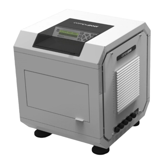
- Page 1 E-Series Commercial Saltwater Chlorine Generator Owner’s Manual 2012 E-Series Owners Manual AU - V2.docx Compu Pool E-Series Manual...
-
Page 2: General Product Specification
For assistance please contact the Compu Pool: Phone Number: +61 (0)7 5596 3773 9:00am - 5:00pm EST Manufactured by: Compu Pool Products 3-7 Hilldon Court, Nerang QLD 4211 Phone: +61 (0)7 5596 3773 Fax: +61 (0)7 5596 1951 www.compupool.com.au Compu Pool E-Series Manual... -
Page 3: Safety Instructions
Maintaining high chlorine and very high salt levels above the recommended range can contribute to corrosion of pool (and/or spa) equipment. 2.1.9 Check the expiration date of any water chemistry test kits as test results may be inaccurate if used after that date. Compu Pool E-Series Manual... -
Page 4: Table Of Contents
THE CHEMISTRY INVOLVED ................6 WATER CHEMISTRY ..................6 ADDING SALT TO POOL OR SPA ..............9 INSTALLATION ....................10 INSTALLATION CHECKLIST ................19 10.0 USING THE CONTROL PANEL ................ 19 11.0 MAINTENANCE ....................21 12.0 WARRANTY ...................... 23 Compu Pool E-Series Manual... -
Page 5: Introduction
3.0 INTRODUCTION 3.1.1 Congratulations on the recent purchase of a Compu Pool Products E-Series Commercial Saltwater Chlorine Generator. Please take a moment to read through the entire manual before installing the new unit. The generator must be installed and operated as specified. -
Page 6: The Chemistry Involved
5.0 THE CHEMISTRY INVOLVED 5.1.1 The E-Series Commercial Chlorine Generator by electrolysis creates chlorine to sanitize the pool using the salt (NaCL) in the water. A small electric charge is applied across a set of titanium plates inside the Electrolytic Cell(s). This produces Sodium Hypochlorite (NaOCl). - Page 7 Increase chlorine production when temperature goes up. 6.4.3 Increase chlorine production when number of pool users goes up. 6.4.4 Use Stabilizer (Cyanuric Acid) to protect free chlorine in the pool. 6.4.5 Decrease chlorine production when temperature goes down. Compu Pool E-Series Manual...
- Page 8 Combined Chlorine. Weak chlorine which is combined with the contaminants in the water. 6.6.5 Free Chlorine. Active chlorine in the water with the potency to destroy contaminants. 6.6.6 Shock Treatment. The removal by means of oxidation of those materials that have chlorine demand. Compu Pool E-Series Manual...
-
Page 9: Adding Salt To Pool Or Spa
Salt Level 7.3.1 The Compu Pool E-Series chlorinator can work with a broad salinity range, from a minimum of 3000 ppm (parts per million), up to 6000 ppm. However, the ideal level for operation is 3500 ppm. To achieve this level of salinity, add 3.5kg. of salt for every 1000 litres of water. -
Page 10: Installation
8.0 INSTALLATION Positioning 8.1.1 WARNING: The E-Series chlorinator must be installed in a dry and well ventilated room or area that is protected from the environment, rain and direct sunlight. The chlorinator must not be installed into a location that is used for chemical storage as this will void the warranty. - Page 11 This will allow for mounting keyhole apertures. Push the screw heads through the apertures and let them fall into onto the bracket keyhole details. the slot. The Electronics Module should now be securely mounted. Compu Pool E-Series Manual...
- Page 12 Use strong screws shipping, it will be pre-assembled to the or bolts to fasten the Bracket to the Mounting Bracket. The Cell Module will mounting surface. need to be removed from the Mounting Bracket to undertake this installation. Compu Pool E-Series Manual...
- Page 13 Ensure that the Cell Collar is tightly assembled to the Cell Housing prior to this. 8.4.8 The E-Series Chlorinator has been designed to operate with a maximum working pressure of 40Psi (275kPa). Damage to the Cell Module may occur if the working pressure exceeds this limit.
- Page 14 MAIN FLOW RETURN LINE (TO POOL) M2 VALVE (OUTLET) M3 VALVE FLOW M1 VALVE SENSOR (INLET) MAIN FLOW RETURN LINE (FROM FILTRATION) 8.4.9 Figure 1: Plumbing Diagram Compu Pool E-Series Manual...
- Page 15 The E-Series unit will need to be connected to the power source with a cable that meets local and National Electrical Code(s). The 220-240VAC input must be connected by carrying out the following procedure by a qualified electrician.
- Page 16 (E). Refer to Figure 3 - Terminal Wiring Diagram, for correct wiring positions. 07. Replace the Circuit Breaker Access 08. Check that earthing conforms to Panel and the Circuit Breaker Door. required standards and codes. Replace the Electronics Module Access Panel (right side). Compu Pool E-Series Manual...
- Page 17 8.5.3). To reduce the risk of electrical shock, this terminal must be connected to the grounding means provided in the electrical supply. 8.5.10 WARNING: Installation of electrical wiring should only be performed by a qualified electrician. Failure to do so could result in serious harm and electrocution. Compu Pool E-Series Manual...
- Page 18 Neutral to Door Fan Breaker Neutral From Circuit Neutral to Transformer Breaker Transformer Output Transformer Input Transformer Output Transformer Input Switchmode Switchmode Positive Positive Out Cell Positive Switchmode Positive Switchmode Switchmode Negative Negative Out Cell Negative Switchmode Negative Compu Pool E-Series Manual...
-
Page 19: Installation Checklist
1. On / Off. For normal operation, the system should be left in the “On” position. In this position the Compu Pool E-Series will produce chlorine according to the desired output %. Simply press the button again to turn the unit off. - Page 20 10.2.2 Water Flow. The water flow warning LED will be illuminated if the flow sensor detects no flow. Chlorine production will only occur when water flow is detected. 10.2.3 Low Salt. The Compu Pool E-Series will automatically let you know if the salinity concentration has fallen below acceptable levels. The warning LED will be illuminated when salt levels fall below 2500ppm.
-
Page 21: Maintenance
11.3.4 Do not use any sharp or metallic objects to remove scale. Scraping or scratching the cell plate's edge or surface will allow chemical attack of the plate, cause premature failure of the cell and will void the warranty. Compu Pool E-Series Manual... - Page 22 Ensure that the cell head collar is screwed down tightly and that the nuts clamping the cell leads to the cell head are tight (see 8.5.7). Compu Pool E-Series Manual...
-
Page 23: Warranty
12.0 WARRANTY 12.1 Warranty Terms 12.1.1 Compu Pool E-Series chlorine generators carry the following two year warranty should fault occur due to faulty manufacturing or materials. 12.1.2 Compu Pool warrants the original purchaser that the equipment shall be free of... - Page 24 12.4.1 Please complete the information below at time of installation and retain in the event you need to file a warranty claim. Model Number Voltage Electronics Module Serial Number Cell Module Serial Number(s) Purchase Date Purchased From Installation Date Installer Installation Address Compu Pool E-Series Manual...
Need help?
Do you have a question about the E-Series and is the answer not in the manual?
Questions and answers