
Related Manuals for SGS SSB500

Summary of Contents for SGS SSB500
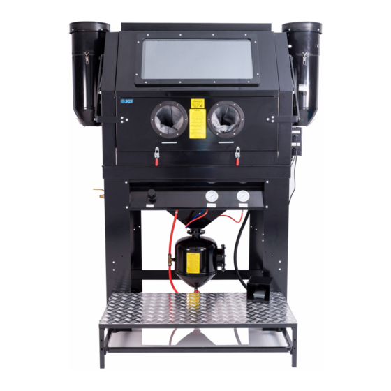
- Page 1 SSB500 HIGH PRESSURE ABRASIVE BLAST CABINET OWNER’S MANUAL FOR YOUR SAFETY PLEASE READ THESE INSTRUCTIONS CAREFULLY AND RETAIN THEM FOR FUTURE USE.
-
Page 2: Specification
SPECIFICATION GENERAL SAFETY INFORMATION MODEL No SSB500 Before installing the machine, ensure the MAX WORK PRESSURE 110 PSI / 7.6 BAR availability and proximity of the required power WEIGHT 220 kg supply. If an existing circuit does not meet the... -
Page 3: Operating Information
A grounded wire attached to the nozzle retainer will safely remove the static electricity. abrasive to recycle back into the tank. WWW.SGS-ENGINEERING.COM PAGE 4 PAGE 5... - Page 4 • To change abrasive, place nozzle end of the hose in a woven bag and depress the foot pedal until all abrasive is removed from the unit. • Discharge water separator as needed. Minimum 1-2 times daily. WWW.SGS-ENGINEERING.COM PAGE 6 PAGE 7...
-
Page 5: Parts Diagram
PARTS DIAGRAM PARTS DIAGRAM WWW.SGS-ENGINEERING.COM PAGE 8 PAGE 9... -
Page 6: Parts List
Moisture Separator 905995 Lamp Housing 905959 LED Light 905960 Right-angle Quick Coupling 905996 Light Lens 905961 Air Hose 905997 Light Lens Underlay 905962 Rubber Seal of Light Lens 905963 Cover Plate 905964 Main Support Pole 905965 WWW.SGS-ENGINEERING.COM PAGE 10 PAGE 11... - Page 7 906011 φ8 Air Pipe 11-15 906012 φ8 Air Pipe 11-16 906013 φ8 Air Hose 11-17/H1 906014 φ8 Air Hose 11-18/H2 906015 φ8 Air Hose 11-19/H3 906016 φ16 Air Hose 11-20/H4 906017 11-21 G1/8” Muffler 906018 WWW.SGS-ENGINEERING.COM PAGE 12 PAGE 13...
- Page 8 Inlet Welding Assembly 906034 12-17 Closure Gasket 906035 12-18 Bolt M8*25 906036 12-19 Rubber Gasket 906037 12-20/C1 G1/4” Straight Coupling 906038 12-21 G1/2” 16 Straight Coupling 906039 12-C2 G1/8” Straight Coupling 906040 12-C3 G1/8” Straight Coupling 906041 WWW.SGS-ENGINEERING.COM PAGE 14 PAGE 15...
- Page 9 M6x12 mm bolt, by using M8x20 mm bolts, flat 48 x Flat washer 8 a flat washer and a M6 nut in washers, lock washers and M8 32 x Lock washer 8 this sequence. nuts. WWW.SGS-ENGINEERING.COM PAGE 16 PAGE 17...
- Page 10 (including 4 x M8 Nut for tank. bolt, flat washer, lock washer 4 x Flat washer 8 and nut) and rubber seal onto 4 x Lock washer 8 the funnel. 1 x Rubber Gasket WWW.SGS-ENGINEERING.COM PAGE 18 PAGE 19...
- Page 11 Step 6. Place #6 grid cover and insert the discharge hose #9 Cylinder Block for tank in the rear, and then assemble #52 into the protective cover. abrasive hose with tee joint and install the discharge hose thorugh the rubber retainer as shown. WWW.SGS-ENGINEERING.COM PAGE 20 PAGE 21...
- Page 12 Connect the orange hose (16mm) from Electromagnetic valve foam to the funnel as shown. 1(#2) on control panel straight to #21 G1/2”-16, as illustrated in the diagram: H4-C4. Note: to release the hose, push the plastic ring inward. WWW.SGS-ENGINEERING.COM PAGE 22 PAGE 23...
- Page 13 M6 nuts. door, assemble the cabinet and funnel with the M6x16 b. Connect the abrasive hose to #4 abrasive tee joint and mm bolts and 6 flat washers seal thread with Teflon tape. WWW.SGS-ENGINEERING.COM PAGE 24 PAGE 25...
- Page 14 Step 11. Install nozzle retainer to end of the abrasive hose, collectors (#20) on both sides 8 x M6x12 mm Bolt fasten the abrasive hose with 4.2x10 mm tapping screws. of the cabinet assembly #1 with M6x12 mm bolts (8PCS). WWW.SGS-ENGINEERING.COM PAGE 26 PAGE 27...
- Page 15 M8x45 mm bolts, M8 nuts, 8 8 x Flat Washer Nut, 8 flat washer and 8 lock 12 x M8 Nut flat washers and 8 lock 4 x Lock Washer washer. 24 x Flat Washer washers. 12 x Lock Washer WWW.SGS-ENGINEERING.COM PAGE 28 PAGE 29...
- Page 16 ASSEMBLY INSTRUCTIONS SEALING HEAD REPLACEMENT GRAPHICS Step 14: Plug the electromagnetic valve plug and foot pedal plug into the power supply. WWW.SGS-ENGINEERING.COM PAGE 30 PAGE 31...
-
Page 17: Wiring Diagram
WIRING DIAGRAM DC WITH POWER SWITCH WIRING DIAGRAM WWW.SGS-ENGINEERING.COM PAGE 32 PAGE 33... - Page 18 SGS Engineering (UK) Ltd ASSEMBLED DIMENSIONS West Side Park Raynesway Derby, DE21 7AZ EC Declaration of Conformity This is an important document and should be retained MANUFACTURER’S NAME: SGS Engineering (UK) Ltd SHOT BLASTER CABINET TYPE OF EQUIPMENT: SSB500 PART NUMBER:...
Need help?
Do you have a question about the SSB500 and is the answer not in the manual?
Questions and answers
how much abrasive do i put in the blast cabinet
The recommended amount of abrasive is not specified exactly, but the manual advises not to add too much abrasive material, as this may cause the sealing head not to seal properly.
This answer is automatically generated