
Related Manuals for ADB WARP Colour Changer


Summary of Contents for ADB WARP Colour Changer
- Page 1 WARP Colour Changer - CC/W User Manual Issue 2.0 Lighting Technologies M 6043 1106.06.043...
-
Page 3: Table Of Contents
Index Index INDEX ..............................1 PRODUCT OVERVIEW ....................... 2 PRODUCT DESCRIPTION ......................3 2.1........................3 ONSTRUCTION 2.2........................3 OTOR AND 2.3........................3 OLOUR ILTERS 2.4........................ 3 CROLLING ODES 2.5..................... 3 OLOUR CHANGING SPEED 2.6........................... 3 ESET 2.7. -
Page 4: Product Overview
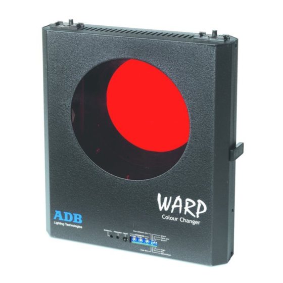
Product overview 1. Product overview User Manual - page 2 www.adblighting.com Issue 2.0... -
Page 5: Product Description
Product description 2. Product description 2.1 Construction The housing of the WARP Colour Changer is made of sturdy aluminium plate to reduce weight. Outer finish is a scratch resistant matt black epoxy powder coating. 2.2 Motor and Fan The scrolling of the gel string is controlled by 2 DC Servo Motors which are mounted directly to the plastic rollers. -
Page 6: System Configuration
Product description 2.7 System Configuration The XLR4 connector on the motor-house provides DMX data and Power Supply (24V DC / 1A) for CC/WARP. Adding the CC/WARP • Insert the changer into the WARP/M. • Connect the safety cable. • Connect the XLR4 cable •... -
Page 7: Operation
Operation 3. Operation For normal operation, set the DIP switches to the desired configuration and set the rotary address switch to the desired DMX address. Set power and the unit is now ready to work. 3.1 LED Indicators Description Red power LED Red LED lights up when DC power is applied to the unit. -
Page 8: Fan Speed
Operation FAN SPEED Switch 1 Description LOW fan speed HIGH fan speed CONTINUOUS /STEP mode Description Switch 2 STEP mode The movement of the gel string is divided into 16 steps, and each step corresponds to a separate colour. For approximately every 6.7% change of intensity level of the signal on the control channel, the gel string will change one colour CONTINUOUS mode... -
Page 9: Special Operation Mode
Special operation mode 4. Special operation mode 4.1 Remote reset address If during normal operation the positioning of the gel string is incorrect, it is possible to bring it back to the correct position by sending a RESET signal from a control console. This function is especially useful if the unit is installed in a difficult to reach position. -
Page 10: How To Get The Best Performance
Special operation mode Attention: A factory reset may become necessary in cases when the Colour Changer does function correctly. E.g. case ventilators controllable and run constantly. 4.5 How to get the best performance 1. Maximum ambient temperature is 50° C. 2. -
Page 11: Maintenance
Maintenance 5. Maintenance 5.1 Cleaning The colour changer uses optical encoding to calculate the position of the colour filter. If dust accumulates on the optical devices, the accuracy in the positioning of the colour filter will be degraded. Refer to the following steps to clean the optical encoding units if needed: 1. -
Page 12: How To Replace A Gel String
Maintenance Use High Temperature Transparent Polyester adhesive tape (e.g. 3M #853) to join the colour filters side by side. Make sure that there is a good adhesion by pressing firmly on the tape against the filters. Join the first and the last colour filter to the rollers. You can use the reference line marked on the roller for alignment. -
Page 13: Specifcations
Specifications 6. Specifcations Power consumption 200 W max. Control input from CC/W Output to CC/W colour changers (CC/W - 4 Pin XLR male connector) Operating environment Indoor use only (NOT Waterproof) Operating environment temp 0° C - 50° C Size Weight 2.3 kg Front aperture Ø... -
Page 14: Standards
Standards 7. Standards 7.1 Safety standards Conforms to council directive 73/23/EEC Safety standards (Low Voltage Directive) of CE marking 99 EN60598-1 Luminaries Part 1: general requirements and tests EN60598-2-17 Luminaries Part 2 : particular requirements section luminaries stage lighting, television, film photographic studios... -
Page 15: Personal Notes
8. Personal Notes www.adblighting.com User Manual - page 13 Issue 2.0... - Page 17 ADB - Your Partner for Light Belgium N.V. ADB-TTV Technologies S.A. (Group Headquarters) Leuvensesteenweg 585, B-1930 Zaventem Tel : +32.2.709.32.11, Fax : +32.2.709.32.80, E-Mail : adb@adblighting.com France ADB S.A.S. Sales Office: 92, Avenue Jean Jaurès F-92120 Montrouge Tel : +33.1.41.17.48.50, Fax : +33.1.42.53.54.76, E-Mail : adb.fr@adblighting.com Factory &...
Need help?
Do you have a question about the WARP Colour Changer and is the answer not in the manual?
Questions and answers