Table of Contents
Advertisement
Quick Links
Lithium-Ion Phosphate Battery
PowerCube-X1 Product Manual
Information Version: 3.0
No. 73, Lane 887, ZuChongzhi Road, Zhangjiang Hi-Tech Park
Pudong, Shanghai 201203, China Zip Code: 201203
1 / 23
Pylon Technologies Co., Ltd.
Email:
service@pylontech.com.cn
Website:
http://www.pylontech.com.cn
Tel: 021-51317697
Fax: 021-51317698
17PIXV1101
Advertisement
Table of Contents

Related Manuals for Pylon Technologies PowerCube-X1


Summary of Contents for Pylon Technologies PowerCube-X1
- Page 1 Lithium-Ion Phosphate Battery PowerCube-X1 Product Manual Information Version: 3.0 Pylon Technologies Co., Ltd. No. 73, Lane 887, ZuChongzhi Road, Zhangjiang Hi-Tech Park Pudong, Shanghai 201203, China Zip Code: 201203 Tel: 021-51317697 Fax: 021-51317698 Email: service@pylontech.com.cn Website: http://www.pylontech.com.cn 1 / 23...
-
Page 2: Table Of Contents
This manual introduces PowerCube-X1 from Pylontech. PowerCube-X1 is a high voltage Lithium-Ion Phosphate Battery storage system. Please read this manual before you install the battery and follow the instruction carefully during the installation process. Any confusion, please contact Pylontech immediately for advice and clarification. -
Page 3: Safe Handling Of Lithium Batteries Guide
1. Safe handling of lithium batteries Guide Warning: This product is a high voltage DC system, operated by authorized person only. Warning Before Connecting 1) After unpacking, please check product and packing list first, if product is damaged or lack of parts, please contact with the local retailer; 2) Before installation, be sure to cut off the grid power and make sure the battery is in the turned-off mode;... - Page 4 eminded Please rea ad the user manual ca refully (in th he accessor ries); If the batt tery is stored d for long t ime , it is re equired to c charge them m every six months, an the SOC s hould be no o less than 8 80%;...
-
Page 5: Introduction
2. Introduction PowerCube-X1 is a high voltage battery storage system based on lithium iron phosphate battery, is one of new energy storage products developed and produced by Pylontech, it can be used to support reliable power for various types of equipments and systems. PowerCube-X1 is especially suitable for application scene of high power, limited installation space, restricted load-bearing and long cycle life. -
Page 6: Specifications
2.2 Sp pecification 2.2.1 B Battery Syst 6 / 23 17PIXV110 01... -
Page 7: Battery System
PowerCube-X1 Item (336V50AH) Cell Technology Li-ion (LFP) Battery System Capacity (kWh) 16.8 Battery System Voltage (V Battery System Capacity (Ah) Battery Controller Name SC0500-100 Battery Module Name H48050 Battery Module Quantity (pcs) Battery Module Capacity (kWh) 2.40 Battery Module Voltage (V... -
Page 8: Battery Module
2.2.2 B Battery Mod dule Product T Type H48050A A-15S l Technolog Li-ion ( LFP) tery Module e Capacity (kWh) tery Module e Voltage (V Vdc) tery Module e Capacity (AH) tery Module e Quantity ( (pcs) tery Cell Ca apacity (Wh tery Cell Vo oltage (Vdc... -
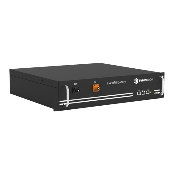
Page 9: Battery Module Front Interface
Battery Module Front Interface Power Terminal +/- To connect battery series power cables. Status ● ● ● Status light: to show the battery module’s status (RUN , Alarm and Protection RS232 Terminal Console Communication Terminal: (RJ45 port) follow RS232 protocol, for manufacturer or professional engineer to debug or service. -
Page 10: Control Module (Internal Power Supply)
2.2.3 Control Module (internal power supply) Control Module has two types: internal and external power supply. Control Module (SC0500A-100S) Front Interface Power Terminal +/- To connect battery power cables in series. Power Switch Switch the battery system’s (control module and high voltage DC power) ON/OFF. External Power Terminal +/- Connect battery system with Inverter. -
Page 11: Definition Of Rj45 Port Pin
485 Commu unication Te rminal: (RJ4 45 port) follo ow RS485 pr rotocol, for c communica ation tween batte ery system a and Inverter RS232 Terminal nsole Com munication n Terminal: (RJ45 port) ) follow RS2 232 protoco ol, for man nufacturer o ofessional en ngineer to d... - Page 12 Flash Indicates save power Normal mode. Standby Indicates the battery is Alarm Light low. Flash Standby Normal Indicates Standby The highest capacity The highest capacity Normal Light indicator LED flashes indicator LED flashes Alarm Light (flash 2), others lighting (flash 2), others lighting Charge Stop charging, PRC Protection...
-
Page 13: Rd Level Control Module (Mbms)
2.2.4 Level C Control Mod dule (MBMS MBMS is the contr roller for mu ultiple battery y piles in pa arallel conn nection. If the p power supp ly is 220Vac c, an adapt or (220Vac to 12Vdc) w will be provid ded. -
Page 14: Definition Of Rj45 Port Pin
CAN / / RS485 RS485; CA AN Commun nication Term minal: (RJ45 5 port) follow w CAN prot tocol, for co ommunicati on betwee ttery system m and PCS. 485 Commu unication Te rminal: (RJ4 45 port) follo ow RS485 pr rotocol, for c communica ation... - Page 15 Flash Standby Normal Indicates Standby Normal Light The highest capacity indicator LED flashes (flash 2), others lighting Charge Alarm Light Stop charging, ALM Protection Light lighting Flash Indicate based on Normal capacity Discharge Stop discharging, ALM Protection Light Light lighting Note: The flashing instructions, flash 1 - light 0.25s / off 3.75 seconds;...
-
Page 16: Installation
3. Installation 3.1 Tools The following tools are required to install the battery pack Wire Cutter Crimping Modular Plier Screw Driver Set NOTE Use properly insulated tools to prevent accidental electric shock or short circuits. If insulated tools are not available, cover the entire exposed metal surfaces of the available tools, except their tips, with electrical tape. - Page 17 Power Cable - (Connection for Black/1.5m/4AWG/2 Black Surlok Battery Series - to Control Terminal Module -) Power Cable (Battery Module Orange/0.18m/4AWG/1 Orange & Serial Connection) 1 Black Surlok Terminal Battery Cascade Black/0.18m/8 Core Super 5th Communication Cable (0.18m) Class Twisted-pair Wire/RJ45 External Battery CAN Black/3.5m/Super 5th Class Communication Cable (direct)
-
Page 18: Installation Location
Lock Button during pulling out the power plug. Grounding: The PowerCube-X1 modules are grounding based on metal direct touch between the module’s surface and rack’s surface. So it needn’t grounding cables at all. If uses normal rack, it can remove the paint at the corresponding place. -
Page 19: Installation
he ambient temperatur re is within t the range fr rom 0°C to 5 50°C. he tempera ture and hu umidity is ma aintained a at a constan nt level. here is minim mal dust and d dirt in the area. - Page 20 B. System turn On Double check all the power cables and communication cables. Make sure the voltage of the Inverter is same level with the battery system. (1) Switch battery system switch on. All the control modules and the battery modules’ green LED light (status and capacity) as below will be on: If all the LED light on as normal, which means the battery system is good and working.
-
Page 21: Trouble Shooting Steps
5. Trouble Shooting Steps 1) If the system is turned on, and the status LED of Control Module is red, but the status LED of Battery Module is green. Please check the External Battery Communication Cable (CAN/RS485) connection is right or not. 2) If the system is turned on, and the status LED of Control Module is fleshing in red, the battery system self check can’t detected. -
Page 22: Emergency Situations
6. Emergency Situations 1) Leaking Batteries If the battery pack leaks electrolyte, avoid contact with the leaking liquid or gas. If one is exposed to the leaked substance, immediately perform the actions described below. Inhalation: Evacuate the contaminated area, and seek medical attention. Contact with eyes: Rinse eyes with flowing water for 15 minutes, and seek medical attention. - Page 23 Pylon Technologies Co., Ltd. No. 73, Lane 887, ZuChongzhi Road, Zhangjiang Hi-Tech Park Pudong, Shanghai 201203, China T+86-21-51317697 | +86-21-51317698 Eservice@pylontech.com.cn Wwww.pylontech.com.cn 23 / 23 17PIXV1101...
Need help?
Do you have a question about the PowerCube-X1 and is the answer not in the manual?
Questions and answers