Table of Contents
Advertisement
Quick Links
Advertisement
Table of Contents

Related Manuals for Ecotech GTS Control Logic RIV-601P/S

Summary of Contents for Ecotech GTS Control Logic RIV-601P/S
- Page 1 SPARK DETECTORS technical description application manual DESP-MASP rev. 8 APR18 ECOTECH GTS SRL Via del Plan del Sant, 24 38012 Predaia Fraz. Mollaro (TN) P.IVA 02553340221 Tel. 0463 461049 |Fax 0463 461375 info@ecotechgts.com www.ecotechgts.com...
-
Page 3: Table Of Contents
SPARK DETECTORS SUMMARY technical description (DESP) Page • Spark detection and extinguishing systems components ............5 DESP • RIV-601P/S Spark detector .....................7 DESP • SAM-871 Mounting frame ...................9 DESP • PAN-701 Spark alarm panel ..................11 DESP • PAN-705M Spark control panel ...................13 DESP •... -
Page 5: Technical Description
SPARK DETECTORS technical description DESP-GB... - Page 7 SPARK DETECTORS technical description SUMMARY Page • Spark detection and extinguishing systems components ....... 5 DESP • RIV-601P/S Spark detector ............... 7 DESP • SAM-871 Mounting frame ..............9 DESP • PAN-701 Spark alarm panel ..............11 DESP • PAN-705M Spark control panel ..............
-
Page 8: Spark Detection And Extinguishing Systems Components
SPARK DETECTION AND EXTINGUISHING SYSTEMS COMPONENTS RIV-601P/S SAM-871 SPARK MOUNTING FRAME DETECTOR FOR RIV-601P/S page DESP 9 page DESP 7 PAN-705M PAN-701 SPARK CONTROL SPARK ALARM PANEL PANEL page DESP 11 (see FOE 38 electrical wiring) page DESP 13 EVS-811 SNA-808L WATER ALARM SOUNDER... -
Page 9: Ugn-820A Axial Spray Nozzle
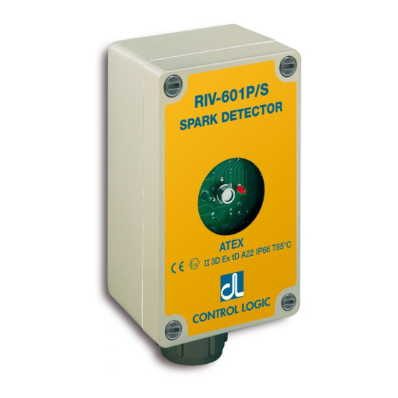
SPARK DETECTION AND EXTINGUISHING SYSTEMS COMPONENTS UGN-820A AXIAL SPRAY NOZZLE UGN-820 SPRAY NOZZLE page DESP 20 page DESP 19 UGN-820P LAM-612P FLAT JET SPRAY EXTERNAL TEST NOZZLE LAMP page DESP 21 page DESP 23 SER-852 SER-851 GATE TYPE BUTTERFLY TYPE DUCT VALVE DUCT VALVE page DESP 25... - Page 10 II 3D T85°C SPARK DETECTOR RIV-601P/S Description Spark detector RIV-601P/S is an electronic fire alarm device, sensitive When a spark is detected the relay is operated for 3 seconds (time to sparks and incandescent bodies in movement. can be adjusted from 1 to 10 seconds). If the sparks are continuous Its use is particularly recommended on dust collection systems in the relay is operated till 3 seconds after last spark.
- Page 11 SPARK DETECTOR RIV-601P/S Specifications Cast aluminium case IP66 protection (watertight NEMA 4). Power supply 24Vdc (20-30V) filtered (ripple less than 5%). The simplest application of the detector is to activate a sound alarm Current consumption 13mA normal, 50mA in alarm. Test 20mA. and possibly automatic plant mechanisms (stop, reverse direction Spectral sensitivity infrared (IR) 1-3 micron.
- Page 12 MOUNTING FRAME SAM-871 for spark detector RIV-601P/S Specifications Mounting frame SAM-871 is composed of two parts: the base The detector is placed inside among foam rubber walls. to be fixed to the ducting by rivets or self-threading screws, the Material: 1mm thick stainless steel, painted yellow. Dimensions 170x165xH115mm (190x185x130mm package).
- Page 13 MOUNTING FRAME SAM-871 for spark detector RIV-601P/S duct mounting examples Double detector (pair) • • • duct SPARK DETECTORS installed on duct Single detector Mounting holes on ducting (dimensions in mm) Ø 62 No. 6 holes with appropriate size for the type of mounting (rivets, self-threading screws or other) taking into consideration that the...
- Page 14 SPARK ALARM PANEL PAN-701 for spark detector RIV-601P/S It carries on the front panel a 24Vdc power indicator green LED, a reverse polarity indicator red LED, an overload/short circuit indicator yellow LED, 2 indicator red LEDs for the alarm of the Spark Detectors, 2 TEST buttons and 2 RESET buttons.
- Page 15 SPARK DETECTOR SYSTEM APPLICATION EXAMPLE Monitoring Extinguishing Detection Duct valve Silo Air outlet Dust collection system Alarm sounder beacon Control panel Machine DESP 12-GB rev. 1 OCT13...
- Page 16 SPARK CONTROL PANEL PAN-705M for spark detector RIV-601P/S The control panel PAN-705M is designed to operate and monitor all the functions of a complete spark detector system. On front panel it displays the operating state of the spark detectors that control the extinguishing and the monitoring functions, the nozzle water flow switch, the STOP function and the power voltage.
- Page 17 SPARK CONTROL PANEL PAN-705M for spark detector RIV-601P/S Electrical diagram The front panel should not be hung by the internal 1.5A THERMAL CIRCUIT BREAKER (TCB) electrical connections. In the event of overload or short circuit it automatically interrupts When you open the control the current ow.
- Page 18 ALARM SOUNDER BEACON SNA-808L Specifications Audible visual alarm. Indoor and outdoor use. IP65 protection. Power voltage 24Vdc 16 mA 0,4W. Electrical wiring on screw terminals. Alternating sound 101dB(A), lamp flash 1Hz. Operating temperature -10 +55°C. Dimensions Ø 93xH110mm. Packaging 100x100x110mm. Weight 290g (320g with packaging).
- Page 19 ALARM LAMP LAC-843 Specifications Lamp with built-in 1Hz flasher. Wall mounting. Power voltage 24Vdc 3-5mA. Electrical wiring on screw terminals. IP65 protection. Operating temperature -10 +60°C. Dimensions Ø 93 x h 80mm. Packaging 100x100x85mm. Weight 120g (160g with packaging). Ø 93 STRAINER FOR WATER SOLENOID VALVE FIL-817...
- Page 20 II 3D T135°C WATER FLOW SWITCH PAC-846 Designed to monitor the spray water flow in the UGN-820 (or other type) nozzle during the extinguishing operation. Installed upstream of the EVS-811 solenoid valve. When a water flow is detected then a contact is closed on the BLUE and BLACK leads.
- Page 21 AIR PURGING UNIT APU-874 Description The air purging unit model APU-874 is a mechanical unit designed to be applied in front of the spark detector RIV-601P/S mounting unit SAM-871 for application on ducts and conveyors in order to perform 3/8”M air fitting two important functions: •...
- Page 22 STANDARD SPRAY NOZZLE UGN-820 Specifications Jam-proof design, vortex type. 120° hollow cone jet. Spray at right-angle from water entry. Flow rate 13 lt/min (0.2 lt/sec) at 1 bar, 26 lt/min (0,4 lt/sec) at 4 bar. Coupling 3/4" gas female. Case material brass. To be mounted at right-angle to spray, on center of ductwork.
- Page 23 AXIAL SPRAY NOZZLE UGN-820A Specifications To be mounted on surface of ductwork. It is used in applications where it is necessary to avoid bulky in the duct because of the type and the quantity of transported material (eg fibers, paper, leather). 70°...
- Page 24 FLAT JET SPRAY NOZZLE UGN-820P Specifications To be mounted on surface of ductwork. Used for special applications. 90° flat jet. Spray jet in line with water entry. Flow rate 14 lt/min (0.2 lt/sec) at 1 bar, 28 lt/min (0,4 lt/sec) at 4 bar. Coupling 3/4"...
- Page 25 PULSE COUNTER CON-844 Counts the number of alarms and extinguishing operations. Specifications 5 digits. Manual reset. Panel mount with mounting clip. Power voltage 24Vdc 0.55W. Electrical wiring on free leads. Dimensions 48x64xH24mm. Weight 130g. ELECTRICAL WIRING Panel cut-out RIV-601P/S - T+ S CON-844 To count all the spark detector alarms Control panel...
-
Page 26: Lam-612P External Test Lamp Unit
II 3D T85°C EXTERNAL TEST LAMP UNIT LAM-612P Description Designed to test the RIV-601P/S spark detector window integrity against dust and dirt build-up. Its use is recommended when internal test cannot be reliable because of window being covered or darkened. Its mounted like a spark detector, using the same SAM-871 mounting unit, over the duct in the opposite position, so as it will be in front of the spark detector. - Page 27 EXTERNAL TEST LAMP UNIT LAM-612P OPERATING INSTRUCTIONS The LAM-612P unit is operated when the Test key on the control panel is depressed. The control panel must be independent from the spark detector system control panel. Application with one RIV-601P/S spark detector. This is very important in order that both the external and the (SAM = SAM-871 mounting unit) normal internal test can be performed.
- Page 28 ELECTRO-PNEUMATIC ELECTRO-PNEUMATIC DUCT VALVE SER-851 DUCT VALVE SER-852 butterfly type slide type (or sash type) Diameters from 100 to 800mm Diameters from 100 to 1000mm Galvanized or stainless steel Galvanized or stainless steel Standard or ATEX (zone 22) model Standard or ATEX (zone 22) model Normal air pressure 6 bar Normal air pressure 6 bar Solenoid voltage 24Vcc...
-
Page 29: Application Manual
SPARK DETECTORS application manual MASP-GB... -
Page 31: Spark Detector System General Diagram
SPARK DETECTORS application manual SUMMARY Page • Introduction to Control Logic spark detector system ........5 MASP • Spark detector system general diagram ............6 MASP • Dimensioning of spark detector system ............7 MASP • Mechanical installation of the spark detector system ........8 MASP •... - Page 32 THE CONTROL LOGIC SPARK DETECTOR SYSTEM In addition to the extinguishing operation, it may be advisable The spark detector is used for surveillance of the dust extraction ductwork connected to the silo and to neutralize to close the duct by an electro-pneumatic fire damper valve, mounted downstream from the nozzle and the monitoring every spark before it can ignite the silo.
- Page 33 SPARK DETECTOR SYSTEM system diagram Flange variant control panel PAN-705M alarm sounder beacon SNA-808L Flanges not supplied water in 3-4 bar mounting frame flow switch SAM-871 PAC-846 solenoid valve EVS-811 spark detector spark detector 3/4" pipe RIV-601P/S RIV-601P/S with mounting frame with mounting frame SAM-871 SAM-871...
-
Page 34: Dimensioning Of Spark Detector System
DIMENSIONING OF SPARK DETECTOR SYSTEM The elements to be considered for dimensioning the system In general a pressure of 3-4 bar on the nozzle is recommended. are the following: When the water pressure is not sufficient or unstable, it is •... -
Page 35: Mechanical Installation Of The Spark Detector System
MECHANICAL INSTALLATION OF THE SPARK DETECTOR SYSTEM The problems of mechanical installation are mainly those of the Solenoid valve EVS-811 must be near the nozzle, to minimize spark detector RIV-601P/S and the spray nozzle UGN-820. The the time required by water flowing from valve to nozzle. other components are installed according to general electrical and mechanical rules. - Page 36 MOUNTING OF SPARK DETECTOR RIV-601P/S WITH SAM-871 MOUNTING FRAME The spark detector RIV-601P/S is mounted using the SAM-871 In placing the base over the duct, make sure that the window mounting frame, which consists of a metal case in two parts: aluminum ring enters the duct.
- Page 37 MOUNTING OF SPARK DETECTOR RIV-601P/S WITH SAM-871 MOUNTING FRAME Double detector (pair) • • • duct SPARK DETECTORS installed on duct Spark detector is not installed directly over the duct but through the SAM-871 mounting frame which isolates it from the duct itself. Spark detector is put inside the SAM-871 mounting frame and it sees the duct internal through two optical windows.
- Page 38 INSTALLATION OF SPRAY NOZZLE UGN-820 Spray nozzle UGN-820 is a jam-proof vortex type nozzle, with In “small” ducts (less than 500mm diameter) usually only one a large outlet hole (19mm diameter). It generates a 130° hollow spray nozzle is mounted. cone jet.
-
Page 39: Installation Of Spray Nozzle Ugn-820
INSTALLATION OF SPRAY NOZZLE UGN-820 Flange variant 3/4" pipe water in 3-4 bar flow switch PAC-846 Flanges not supplied EVS-811 solenoid valve 3/4" pipe flange flange duct nozzle nozzle UGN-820 UGN-820 15m from detector standard distance See page MASP 13 for minimum distance between detection and extinguishing rev. - Page 40 DISTANCE BETWEEN SPARK DETECTOR AND SPRAY NOZZLE Standard distance 15 meters The minimum distance is based on 0.2 sec When the available duct length is critical, delay time due to the response delay time of a higher water pressure of 5-6 bar is If duct length is enough, standard distance the solenoid valve and water travelling time suggested.
-
Page 41: Spark Detector System Electrical Connections
SPARK DETECTION SYSTEM ELECTRICAL CONNECTIONS general guidelines The electrical wiring must be made by qualified personnel, and in accordance with local and national rules. It is highly recommended to connect the metallic enclosure body of all the electrical equipment (RIV-601P/S, PAN-705M, PAC-846, EVS-811, etc.) to a good ground line using the ground terminals provided and signaled by ground label... -
Page 42: Spark Detector System Startup
SPARK DETECTOR SYSTEM STARTUP OPERATIONS General considerations Alarm MEMORY function After connections of all system components have been The DET and WATER FLOW alarm signal LEDs remain lit for the made, following the corresponding electric diagram (see page duration of the alarm: DET steady red light for all the alarm time MASP 18 for systems type “A”... -
Page 43: Preventive Maintenance
PREVENTIVE MAINTENANCE Preventive maintenance of the spark detector system is generally not required for the following reasons: • Detectors generally do not get dirty. It has been found that the air flow in the duct keeps the glass window of the detector mounting frame clean. - Page 44 SPARK DETECTOR RIV-601P/S electrical connections The detector case lid is closed by four screws. At each spark detected, the detector is held in alarm for 3 sec. The electrical wiring on the terminal block is to be made following the The internal LED lamp lights up, indicating the relay is energized.
- Page 45 SYSTEMS TYPE “A” AND “B” electrical wiring System type “A” comprises only one detector and one nozzle and it is The PAN-705M control panel allows the simple systems type “A” and used for “small” ducts up to 500mm diameter. “B” expanding, transforming them into complete systems type “E1” System type “B”...
-
Page 46: Systems Type "A" And "B" System Diagram
SYSTEMS TYPE “A” AND “B” Component list: Type “A” Type “B” system diagram n. 1 n. 2 RIV - 601P/S Spark detector n. 1 n. 2 SAM - 871 Mounting frame System type “A” comprises only one spark detector and one n. -
Page 47: Systems Type "A" And "B" Startup Operations
SYSTEMS TYPE “A” AND “B” startup operations List of possible malfunctions It is advisable to put on the front panel of the PAN-705M Control Panel the “NOT PRESENT” labels positioned on the 1) The detector fails to operate with TEST. missed components, e.g. - Page 48 SYSTEMS TYPE “E1” AND “E” The front panel should not be hung by the internal electrical electrical wiring connections. When you open the control panel it is System type “E1” comprises only one extinguishing detector, suggested to place the front one monitoring detector and one nozzle.
-
Page 49: Systems Type "E1" And "E" General Functions
SYSTEMS TYPE “E1” AND “E” • MONITORING DET 3 RED LED Steady light indicates that the monitoring spark detector DET 3 is in general functions alarm state (standard time 3 sec at each spark detected), blinking light (until manual RESET) indicates that there was an alarm. •... - Page 50 SISTEMS TYPE “E1” AND “E” Component list: Type “E1” Type “E” system diagram n. 2 n. 4 RIV - 601P/S Spark detector n. 2 n. 4 SAM - 871 Mounting frame System type “E1” comprises only one extinguishing detector, n. 1 n.
-
Page 51: Systems Type "E1" And "E" Startup Operations
SYSTEMS TYPE “E1” AND “E” startup operations It is advisable to put on the front panel of the PAN-705M List of possible malfunctions: Control Panel the “NOT PRESENT” labels positioned on the missed components, e.g. DET 2 or DET 4, etc. (see page DESP 1) The detector fails to operate with TEST. -
Page 52: Important Warning Notices
IMPORTANT WARNING NOTICES The Control Panel must be powered by an external Excess water power supply connected to the fan control panel Excessive extinguishing water entering the duct could downstream from the manual main on-off fan switch result in silo flooding, or worse, in damaging sensitive and upstream from the automatic start-stop fan switch, electrical equipment, such as fan motors, etc. -
Page 53: False Alarms From Electromagnetic Emissions
FALSE ALARMS FROM ELECTROMAGNETIC EMISSIONS 1.0 Introduction Fig. 1 - Electrical arc between two electrical contacts while they are Control Logic Spark Detectors are designed and certified for opening an electromagnetic immunity level greater than required by CE norms (EMC directive). If other electrical equipment present in the plant have an electromagnetic emission level lower than required by CE norms, false alarms are not expected. - Page 54 FALSE ALARMS FROM ELECTROMAGNETIC EMISSIONS 3.0 Sources of electromagnetic emissions There are lots of electrical equipment which can generate electromagnetic noise. Here is a short list of the main ones. Radio and television transmitters Industrial computers for production processes Their electromagnetic field is modulated by sound and im- Their connection to equipment and other electrical devices age.
- Page 55 FALSE ALARMS FROM ELECTROMAGNETIC EMISSIONS 4.0 How to reduce the electromagnetic noise Stopping electromagnetic noise on spark detector systems It is necessary to prevent noise from reaching the In order to obtain good results and to eliminate or minimize the detector.
- Page 56 FALSE ALARMS FROM ELECTROMAGNETIC EMISSIONS Conclusions Electromagnetic noise pulses, those that are only a fraction of a microsecond in length, are difficult to verify due to their fast, momentary and unpredictable nature. Yet they are the most treacherous ones since they are difficult to verify and can trigger spark detectors false alarms because detector response is very fast.
- Page 57 EU DECLARATION OF CONFORMITY (DoC) This declaration of conformity is issued under the sole responsibility of the manufacturer and belongs to the following products: SYS-A – SYS-B – SYS-E1 – SYS-E Spark detection and extinguishing systems for dust collecting systems SYS-F1A –...
-
Page 58: Ordinary And Extraordinary Maintenance
ORDINARY AND EXTRAORDINARY MAINTENANCE The water pressure which supplies the extinguishing system, All the spark detection and extinguishing system must be composed of flow switch, solenoid valve and nozzles, is periodically verified in order to find faulty operations at least once suggested to be at least 3 bar, so as to keep uniform the water a day. - Page 60 ECOTECH GTS SRL Via del Plan del Sant, 24 38012 Predaia Fraz. Mollaro (TN) P.IVA 02553340221 Tel. 0463 461049 |Fax 0463 461375 info@ecotechgts.com www.ecotechgts.com...
Need help?
Do you have a question about the GTS Control Logic RIV-601P/S and is the answer not in the manual?
Questions and answers