Table of Contents
Advertisement
Quick Links
♦
♦
PRECISION INSTRUMENTS FOR TEST AND MEASUREMENT
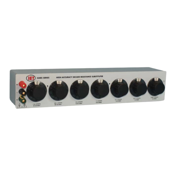
HARS-X and X2
High Accuracy Resistance
Substituter
User and Service Manual
Copyright © 2018 IET Labs, Inc.
Visit www.ietlabs.com for manual revision updates
HARS-X im/October 2018
www.ietlabs.com
IET LABS, INC.
Email: info@ietlabs.com
TEL: (516) 334-5959 • FAX: (516) 334-5988
Advertisement
Table of Contents

Related Manuals for IET Labs HARS-X


Summary of Contents for IET Labs HARS-X
- Page 1 ♦ PRECISION INSTRUMENTS FOR TEST AND MEASUREMENT HARS-X and X2 High Accuracy Resistance Substituter User and Service Manual Copyright © 2018 IET Labs, Inc. Visit www.ietlabs.com for manual revision updates HARS-X im/October 2018 www.ietlabs.com IET LABS, INC. Email: info@ietlabs.com TEL: (516) 334-5959 • FAX: (516) 334-5988...
- Page 2 IET LABS, INC. Email: info@ietlabs.com TEL: (516) 334-5959 • FAX: (516) 334-5988...
- Page 3 HARS-X WARRANTY We warrant that this product is free from defects in material and workmanship and, when properly used, will perform in accordance with applicable IET specifi cations. If within one year after original shipment, it is found not to meet this standard, it will be repaired or, at the option of IET, replaced at no charge when returned to IET.
- Page 4 HARS-X and X2 WARNING OBSERVE ALL SAFETY RULES WHEN WORKING WITH HIGH VOLTAGES OR LINE VOLTAGES. Dangerous voltages may be present inside this instrument. Do not open the case Refer servicing to qualifi ed personnel HIGH VOLTAGES MAY BE PRESENT AT THE TERMINALS OF THIS INSTRUMENT WHENEVER HAZARDOUS VOLTAGES (>...
-
Page 5: Table Of Contents
HARS-X Contents Chapter 1: Introduction 1.1 Introduction ..................1 Chapter 2: Specifi cations Specifi cations ..................2 Ordering Information .................3 Chapter 3: Operation 3.1 Initial Inspection and Setup ............5 3.2 Connection ...................5 3.2.1 General Considerations ............5 3.2.3 Four-Wire Kelvin Lead Connections .........5 3.2.4 Thermal emf Considerations ..........6... - Page 6 HARS-X Figures and Tables Figure 1-1. HARS-X Series High Accuracy Resistance Substituter ..1 Figure 1-2. Single-Decade HARS Unit .............1 Figure 2-1. Typical Operating Guide Affi xed to Unit .......4 Figure 3-1 Optimal 4-Wire Kelvin Lead Connection ........6 Figure 4-1. HARS Series Schematic Diagram ..........8 Table 4-2: Replacement List ..............9...
-
Page 7: Chapter 1: Introduction
HARS-X and X2 Chapter 1 INTRODUCTION With a resolution as low as 1 mΩ and a maximum 1.1 Introduction available resistance of over 111 MΩ, the HARS se- ries may be used for exacting precision measurement The High-Accuracy Resistance Substituter (HARS) -
Page 8: Chapter 2: Specifi Cations
HARS-X and X2 Chapter 2 SPECIFICATIONS For convenience to the user, the pertinent specifi cations are given in an OPERATING GUIDE affi xed to the case of the instrument. Figure 2.1 shows a typical example. SPECIFICATIONS HARS-X HARS-X2 Total Long-term... -
Page 9: Ordering Information
HARS-X and X2 ORDERING INFORMATION Total resistance No of Resolution Total resistance No of Resolution Model* Model* (Ω) Dials (Ω) (Ω) Dials (Ω) HARS-X-1-0.001 HARS-X-4-0.001 0.01 0.001 11.11 0.001 HARS-X-4-0.01 HARS-X-1-0.01 111.1 0.01 0.01 HARS-X-4-0.1 HARS-X-1-0.1 1.111 k HARS-X-1-1 HARS-X-4-1 11.11 k... -
Page 10: Figure 2-1. Typical Operating Guide Affi Xed To Unit
HARS-X and X2 Specifi cations... -
Page 11: Chapter 3: Operation
HARS-X and X2 Chapter 3 OPERATION 3.2.2 Electrical Considerations 3.1 Initial Inspection and Setup In order to make proper use of the full performance This instrument was carefully inspected before ship- capabilities of the HARS unit, especially if low resis- ment. -
Page 12: Thermal Emf Considerations
HARS-X and X2 To determine the resistance obtained when one or more “10” settings are used, simply add “1” to the next higher decade. For example, a setting of 3-6- 10-0-10 Ω becomes: 0 0 0 0 6 0 0 0... -
Page 13: Chapter 4: Maintenance
This can be automatically done in months. This procedure may be carried out by the user many instruments which have an offset subtraction if a calibration capability is available, by IET Labs, capability. or by a certifi ed calibration laboratory. -
Page 14: Schematic
HARS-X and X2 4.2 Schematic Refer to Figure 4-1 for a schematic of the HARS decade unit. Figure 4-1. HARS Series Schematic Diagram Maintenance... -
Page 15: Replaceable Parts List
HARS-X and X2 4.3 Replaceable Parts List Table 4.2: Replacement List Model Ref IET Pt No Description BP-1000-RD Binding Post, Red BP-1000-BK Binding Post, Black BP-1000-GN Binding Post, Green HARS-X-4300-KNB Knob Assembly Not Shown HARS-X-3100 Foot Not Shown HARS-4100-X-.001 1 mΩ/step Decade Switch Assembly Not Shown HARS-4100-X-0.01...
Need help?
Do you have a question about the HARS-X and is the answer not in the manual?
Questions and answers