Advertisement
Quick Links
♦
♦
PRECISION INSTRUMENTS FOR TEST AND MEASUREMENT
1986
Omnical
Sound-Level Calibrator
User and Service Manual
Copyright © 2018 IET Labs, Inc.
Visit www.ietlabs.com for manual revision updates
1986 Instruction Manual Dec. 2018
www.ietlabs.com
IET LABS, INC.
Email: info@ietlabs.com
TEL: (516) 334-5959 • FAX: (516) 334-5988
Advertisement

Subscribe to Our Youtube Channel
Related Manuals for IET Labs 1986 Omnical


Summary of Contents for IET Labs 1986 Omnical
- Page 1 ♦ PRECISION INSTRUMENTS FOR TEST AND MEASUREMENT 1986 Omnical Sound-Level Calibrator User and Service Manual Copyright © 2018 IET Labs, Inc. Visit www.ietlabs.com for manual revision updates 1986 Instruction Manual Dec. 2018 www.ietlabs.com IET LABS, INC. Email: info@ietlabs.com TEL: (516) 334-5959 • FAX: (516) 334-5988...
- Page 2 IET LABS, INC. Email: info@ietlabs.com TEL: (516) 334-5959 • FAX: (516) 334-5988...
- Page 3 1986 WARRANTY We warrant that this product is free from defects in material and workmanship and, when properly used, will perform in accordance with applicable IET specifi cations. If within one year after original shipment, it is found not to meet this standard, it will be repaired or, at the option of IET, replaced at no charge when returned to IET.
- Page 4 1986 Safety Symbols General defi nitions of safety symbols used on the instrument or in manuals are listed below. Caution symbol: the product is marked with this symbol when it is necessary for the user to refer to the instruction manual. Hazardous voltage symbol: the product is marked with this symbol when high voltage maybe present on the product and an electrical shock hazard can exist.
- Page 5 To avoid the danger of introducing additional hazards, do not install substitute parts or perform unauthorized modifi cations to the instrument. Return the instrument to an IET Labs for service and repair to ensure that safety features are maintained in operational condition.
- Page 6 1986 This page is intentionally left blank.
- Page 7 1986 Table of Contents Chapter 1 Introduction 1.1 Overview ....................... 1 Chapter 2 Specifi cations 2.1 Specifi cations ......................2 2.2 Ordering Information .................... 3 Chapter 3 Operation 3.1 Initial Inspection and Setup .................. 5 3.2 Dial Setting ......................5 3.3 Environmental Conditions ..................
- Page 8 1986 This page is intentionally left blank. Condensed Operation...
- Page 9 1986 CONDENSED OPERATING INSTRUCTIONS c. Read level on instrument under test TO ACTIVATE THE INSTRUMENT: Set 1986 controls to 1 kHz, 114 dB and and adjust its calibration control to indicate the CALIBRATED SPL; listen for 1- kHz audible LEVEL selected in step a. tone.
- Page 10 1986 c. Note reference reading on instrument under b. On 1986: set VARIABLE SPL to set crest fctr test. (reference), any FREQUENCY (2 kHz auto- matically generated), adjust LEVEL and SPL ADJUST controls to set reference level at 2 dB d.
- Page 11 1986 Table A MICROPHONE CORRECTIONS* 1·kHz 2-kHz 4-kHz Microphone GR Adaptor Correction Correction Correction Mfr.& Type Used (dB) (dB) (dB) ------------------------------------------------------------------------------------------------------------------------------------ Random-Incidence-Response Microphones: GR 1961-9610 or -9601 none (1 in. electret) GR 1962-9610 or -9601 1987-7061 ( 1/2 in. electret) GR 1971 (1 in.
- Page 12 1986 This page is intentionally left blank.
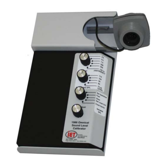
- Page 13 INTRODUCTION 1.1 PURPOSE 1.3 CONTROLS, INDICATORS AND CONNECTORS The GR/IET 1986 Omnical is a comprehensive sound-level calibrator capable of testing all the ba- Figure 1-1 illustrates controls, indicators and con- sic characteristics of a sound-measuring instrument nectors on the GR/IET 1986; Table 1-1 describes with the exception of directivity.
- Page 14 1986 Introduction...
- Page 15 1986 Fig 1-1 Name Description Position(s) Function Reference Provides acoustical Extendable assembly Transducer Stored or output to calibrate containing electro- Assembly extended a sound measuring magnetic transducer instrument 4.5 cm 1 3/4 in. Allows observation of Desiccant Window circular window desiccant indicator Allows storage of Storage...
- Page 16 1986 Fig 1-1 Name Description Position(s) Function Reference Calibrator generates continuous 1 kHz tone slow bursts, each burst has 200 mS duration every 10 s. Calibrator generates a continuous 2 kHz tone at LEVEL selected. Adjust set crest factor with SPL ADJUST knob to set reference for crest factor test Calibrator generates a...
- Page 17 1986 This page is intentionally left blank. Introduction...
- Page 18 1986 This page is intentionally left blank. Introduction...
- Page 19 1986 Chapter 2 SPECIFICATIONS Temperature coeffi cient of sound-pressure level: Less than ±0.02 dB/°C for all frequencies except 4000 Hz For convenience to the user, the pertinent specifi ca- Tone-burst signals: Test signals provided as pre- tions are given in an OPERATING GUIDE affi xed scribed by ANSI S1.4-1971;...
- Page 20 1986 Electrical output: Output provided from nominal 600 Ω and “O” ring for 1 in., 1/2 in. and 1/4 in. shortable source. Voltage proportional to sound pressure; Bruel and Kjaer microphones. Carrying case. 230 mV ±30 mVrms nominal output corresponding to 114 dB SPL - - - - - - - - - - - - - - - - - - - - - - - - - - - - - - - Distortion: <1% THD acoustical or electrical...
Need help?
Do you have a question about the 1986 Omnical and is the answer not in the manual?
Questions and answers