
Related Manuals for DTM System slim III

Summary of Contents for DTM System slim III
- Page 1 v.1.1 FOTOKOMÓRKA NATYNKOWA Instrukcja obsługi i montażu UFPUTZ ICHTSCHRANKE Betriebs- und Montageanleitung PHOTOCELL Operation and assembly manual...
- Page 3 1. Informacje ogólne Fotokomórka składa się z nadajnika i odbiornika. Dostępna w wersji SLIM3 oraz w wersji SLIM3 LED wyposażonej w moduł lampy. Dodatkowa sygnalizacja optyczna pełni funkcję ostrzegawczą oraz pozwala w warunkach słabej widoczności łatwiej zlokalizować wjazd. Odbiornik posiada wyprowadzone styki sterujące typu NC i NO, których obwód zabezpieczony został...
- Page 4 3. Montaż fotokomórki Nadajnik i odbiornik należy zamontować na wysokości 40 - 60 cm od ziemi. Odległość pomiędzy nadajnikiem i odbiornikiem nie powinna być mniejsza niż 1 m. Fotokomórka posiada regulację kąta patrzenia zarówno w odbiorniku jak i w nadajniku. Nie jest wymagany montaż...
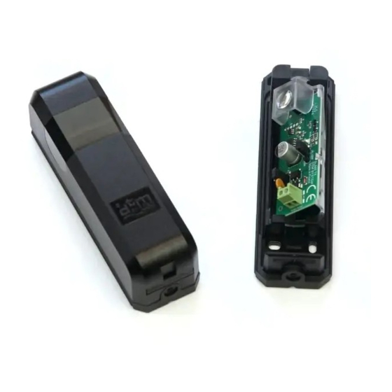
- Page 5 4. Konfiguracja fotokomórki Parametry pracy fotokomórki należy ustawić za pomocą zworek konfiguracji. odbiornik RX nadajnik TX zwora POWER zwora SYNCH zwora przerywacza Rys. 2 Elementy regulacyjne fotokomórki. - zwora SYNCH Konfiguracja funkcji synchronizacji. zwora w pozycji SYNCH OFF - funkcja synchronizacji wyłączona ustawienie dla montażu jednej pary fotokomórek.
- Page 6 - zwora POWER Konfiguracja mocy nadajnika fotokomórki. W przypadku wykorzystywania fotokomórek w miejscu, gdzie mogą występować zakłócenia pracy, spowodowane odbiciami od ścian lub innych przedmiotów, utrudniające wykrycie przeszkody (np. montaż w pomieszczeniach, montaż na bramie garażowej) należy zmniejszyć siłę sygnału w nadajniku ustawiając zworę w pozycji LOW. zwora w pozycji zmniejszona moc sygnału nadajnika, ustawienie dla instalacji, na których występują...
- Page 7 5. Podłączenie elektryczne fotokomórki Fotokomórka współpracuje z centralami sterującymi automatyką bramową. Zaleca się, by instalację elektryczną i podłączenie fotokomórki wykonała osoba z odpowiednimi kwalifikacjami. - Instalacja jednej pary fotokomórek (bez funkcji synchronizacji) Założyć zworki w nadajniku i w odbiorniku w pozycji .
- Page 8 - Instalacja dwóch par fotokomórek (z użyciem funkcji synchronizacji) Wykorzystując funkcję synchronizacji, można zamontować 2 pary fotokomórek z nakładającym się obszarem zasięgu optycznego. Aby wykorzystać funkcję synchronizacji, należy ustawić zworkę w nadajnikach i w SYNCH odbiornikach fotokomórek w pozycji , oraz zasilić je napięciem przemiennym (12- 24VAC).
- Page 9 POWER SYNCH ON OFF SYNCH ON OFF POWER SYNCH ON OFF SYNCH ON OFF...
- Page 10 6. Podłączenie elektryczne lamp sygnalizacyjnych (wersjaSLIM3 LED) Fotokomórki SLIM3 LED posiadają moduły sygnalizacyjne. Lampy przeznaczone są do współpracy z wyjściem sygnalizacyjnym centrali sterującej automatyką bramową. Moduły LED należy podłączyć do wyjścia sygnalizacyjnego o napięciu wyjściowym 12..24V AC/DC. Moduły posiadają wbudowany przerywacz. Jeżeli urządzenie, do którego podłączona jest lampa nie ma wbudowanego przerywacza, można uruchomić...
- Page 11 1.Allgemeine Informationen Die Lichtschranke besteht aus einem Sender und einem Empfänger. Erhältlich in der Version SLIM3 und in derVersion SLIM3 LED, ausgestattet mit einem Lampenmodul. Eine zusätzliche optische Signalisierung dient als Warnfunktion und erleichtert das Auffinden des Eingangs bei schlechten Sichtverhältnissen. Der Empfänger verfügt über Steuerkontakte vom Typ NC und NO, deren Stromkreis durch ein zusätzliches Relais geschützt ist.
- Page 12 3. Montage der Lichtschranke Der Sender und der Empfänger sollten in einer Höhe von 40 - 60 cm über dem Boden montiert werden. Der Abstand zwischen Sender und Empfänger sollte nicht weniger als 1 m betragen. D i e L i c h t s c h r a n k e v e r f ü g t ü b e r e i n e n einstellbaren Blickwinkel sowohl am Empfänger als auch am Sender.
- Page 13 4. Konfiguration der Lichtschranke Die Betriebsparameter der Lichtschranke müssen mit Hilfe der Konfigurationsjumper eingestellt werden. Empfänger RX TX-Sender Steckbrücke POWER Steckbrücke SYNCH Unterbrecherbrücke Abb. 2 Steuerelemente der Lichtschranke. -Steckbrücke SYNCH Konfiguration derSynchronisationsfunktion. Steckbrücke in Position SYNCH Synchronisationsfunktion ausgeschaltet, Einstellung für die Montage eines Lichtschrankenpaares. Steckbrücke in Position SYNCH...
- Page 14 -Steckbrücke POWER Konfiguration derSendeleistung der Lichtschranke. Wenn Sie die Lichtschranke an einem Ort einsetzen, an dem aufgrund von Reflexionen an Wänden oder anderen Objekten Störungen auftreten können, die die Erkennung eines Hindernisses erschweren (z. B. Installation in Räumen, Installation an einem Garagentor), reduzieren Sie die Signalstärke des Senders, indem Sie die Steckbrücke auf die Position LOW setzen.
- Page 15 5. ElektrischerAnschluss der Lichtschranke Die Lichtschranke ist mit den Schalttafeln der Torautomaten verbunden. Es wird empfohlen, die elektrische Installation und den Anschluss der Lichtschranke von einer qualifizierten Person durchführen zu lassen. - Installation eines Lichtschrankenpaares (ohneSynchronisationsfunktion) Bringen Sie die Steckbrücken am Sender und am Empfänger in die Position SYNCH Schließen Sie die 12-24 V AC/DC-Stromversorgung an den Sender und an den Empfänger der...
- Page 16 - Installation von zwei Lichtschrankenpaaren (mitSynchronisierungsfunktion) Mit der Synchronisationsfunktion können 2 Lichtschrankenpaare mit überlappendem optischem Bereich montiert werden. Um die Synchronisationsfunktion zu nutzen, setzen Sie die Steckbrücke auf den SYNCH Sendern und Empfängern der Lichtschranke auf und versorgen Sie sie mit Wechselspannung (12-24VAC).
- Page 17 POWER SYNCH ON OFF SYNCH ON OFF POWER SYNCH ON OFF SYNCH ON OFF...
- Page 18 6. ElektrischerAnschluss derSignalleuchten (VersionSLIM3 LED) Die LED-Lichtschranken SLIM3 sind mit Signalisierungsmodulen ausgestattet. Die Lampen sind für die Interaktion mit dem Meldeausgang der Zentrale der Torautomatik bestimmt. Die LED-Module sollten an einen Meldeausgang mit einer Ausgangsspannung von 12..24V AC/DC angeschlossen werden. Die Module verfügen über einen eingebauten Unterbrecher.Wenn das Gerät, an das die Lampe angeschlossen ist, nicht über einen eingebauten Unterbrecher verfügt, kann der eingebaute Impulsgeber der Lampe aktiviert werden, indem eine Steckbrücke auf das LED-Modul gesetzt wird.
- Page 19 1.General information A photocell consists of a transmitter and a receiver. Available in the SLIM3 version and in the SLIM3 LED version equipped with a lamp module. Additional optical signaling serves as a warning and makes it easier to locate the entrance in conditions of poor visibility.The receiver has NC and NO type control contacts, the circuit of which is protected by an additional relay.
- Page 20 3. Installation of the photocell The transmitter and receiver should be mounted 40 - 60 cm above the ground. The distance between the transmitter and receiver should not be less than 1 m. The photocell has an angle of vision adjustment both in the receiver and in the transmitter.
- Page 21 4.Configuration of the photocell Photocell operating parameters must be set using the configuration jumpers. receiver RX transmitter TX POWER jumper SYNCH jumper breaker jumper Fig. 2 Configuration elements of the photocell. jumper SYNCH Configuring the synchronization function. jumper in the position - synchronization function disabled, SYNCH setting for the installation of one pair of photocells.
- Page 22 jumper POWER Configuration of the photocell transmitter power.When using photocells in a place where there may be interference in operation, caused by reflections from walls or other objects, making it difficult to detect an obstacle (e.g. installation in rooms, installation on a garage door), reduce the signal strength in the transmitter by setting the jumper to the LOW position.
- Page 23 5. Electrical connection of the photocell The photocell works with the gate automation control units. It is recommended that the electrical installation and connection of photocells made a person with appropriate qualifications. - Installation of one pair of photocells (without synchronization function) Place the jumpers in the transmitter and receiver in the position.
- Page 24 - Installation of two pairs of photocells (using the synchronization function) By using the synchronization function, 2 pairs of photocells with an overlapping optical coverage area can be mounted.To use the synchronization function, set the jumper in SYNCH the transmitters and receivers of the photocells to the position, and supply them with alternating voltage (12-24VAC).
- Page 25 POWER SYNCH ON OFF SYNCH ON OFF POWER SYNCH ON OFF SYNCH ON OFF...
-
Page 26: Acceptance Tests
6. Electrical connection of signal lamps (SLIM3 LED version) SLIM3 LED photocells have signaling modules. The lamps are designed to work with the signaling output of the gate automation control unit. LED modules should be connected to the signaling output with an output voltage of 12..24V AC / DC.The modules have a built-in circuit breaker. -
Page 28: Warranty
The full text of the EU declaration of zgodności UE jest dostępny pod Konformitätserklärung ist unter der conformity is available at the adresem internetowym. Internetadresse abrufbar. internet address. DTM System, ul. Brzeska 7, 85-145 Bydgoszcz, Polska, tel. +48 52 340 15 83, www.dtm.pl...
Need help?
Do you have a question about the slim III and is the answer not in the manual?
Questions and answers