Table of Contents
Advertisement
Quick Links
with MultiTalker® and IntelliVox®
System Installation and Operation Manual
Patented under one or more of the following;
No. 4,941,187; 5,903,227; 6,160,496 and 6,493,450, 7,391,877
In certified aircraft, warranty is not valid unless this product is installed by an
Any reproduction or retransmittal of this publication, or any portion thereof, without the expressed written permission of PS En-
gineering, Inc. is strictly prohibited. For further information, contact the Publications Manager at PS Engineering, Inc., 9800
Martel Road, Lenoir City, TN 37772. Phone (865) 988-9800, email contact@ps-engineering.com.
9800 Martel Road
Lenoir City, TN 37772
www.ps-engineering.com
PAC45J
Audio Controller System
Document P/N 200-045-2000
November 2020
Audio Control System with Intercom
FAA - TSO C139a
Authorized PS Engineering dealer.
PS Engineering, Inc. 2020 ©
Copyright Notice
Advertisement
Table of Contents

Related Manuals for PS Engineering PAC45J


Summary of Contents for PS Engineering PAC45J
- Page 1 Any reproduction or retransmittal of this publication, or any portion thereof, without the expressed written permission of PS En- gineering, Inc. is strictly prohibited. For further information, contact the Publications Manager at PS Engineering, Inc., 9800 Martel Road, Lenoir City, TN 37772. Phone (865) 988-9800, email contact@ps-engineering.com.
-
Page 2: Table Of Contents
ECEIVE IGNAL NDICATOR 2.7.11 M ....................... 2-15 USIC UNCTIONS 2.7.12 S ....................2-16 PEAKER LERT UDIO 2.7.13 B ................... 2-16 ACKLIGHT IMMER OLTAGE 2.7.14 O ..................2-16 THER HARED UNCTIONS PAC45J P ..........................2-17 IN ASSIGNMENTS ............................2-18 IRING HECKOUT... - Page 3 ARRANTY .............................. 4-1 ACTORY ERVICE Appendix A – PAC45J Installation Drawings ............A Appendix B – Radio Interconnect Wiring ..............B Appendix C – Intercom Interconnect Wiring ............C Appendix D – Control Head Interconnect Wiring ............ D Appendix E, Unit Connector Wiring Reference ............E J451 C ..............................
-
Page 4: Section I - General Information
Compatible -Gray EQUIPMENT DESCRIPTION The PAC45J is a state-of-the-art audio isolation amplifier and audio selector that contains an automatic voice activated (VOX) intercom system. It can switch up to eight transceivers (COM 1 to 8) and eight navigation receivers (AUX 1 to 8) that can be configured as desired. -
Page 5: Approval Basis Faa Tso
Installation and Operator’s Manual APPROVAL BASIS FAA TSO FAA TSO The PAC45J-series Audio Selector Panels is FAA authorized under TSO C139A (Audio Ampli- fiers). ED-14C/DO-160G (Environmental Conditions and Test Procedures for Airborne Equipment), ED12B/DO-178C, Level C (Software Considerations for Airborne Equipment) and ED- 18/DO-214A (Audio Systems Characteristics and Minimum Operational Performance Standards for Aircraft Audio Systems). -
Page 6: Equipment Supplied
PS Engineering PAC45J Audio Selector Panel and Intercom System Installation and Operator’s Manual Intercom Specifications Intercom Positions: Up to 9 places (with individual IntelliVox® circuits) Distortion: <1% THD @ 200 mW into 150 Mic Freq. Response, ±3 dB: 300 Hz - 6000 Hz... - Page 7 EQUIPMENT REQUIRED BUT NOT SUPPLIED Circuit Breakers: 1 ea.; 5 amp PULL TYPE REQUIRED for HUB45AR, 1 A for CTL45Js Optional Circuit Breakers: 1 ea.; 1 amp PULL TYPE REQUIRED for PAC45J aural alerts, 1 ea. 1 A for failsafe power...
-
Page 8: Configuration
PAC45J Audio Selector Panel and Intercom System Installation and Operator’s Manual Configuration The PAC45J System is comprised of a single PAC45J HUB (HUB45AR) and up to four CTL45J or a com- bination of CTL45A Control Heads “building blocks” to facilitate flexibility as well as simplicity. Bluetooth... -
Page 9: License Requirements
PS Engineering PAC45J Audio Selector Panel and Intercom System Installation and Operator’s Manual Telephone COM1-8 Cockpit NAV 1-2 Marker1-2 CVR P ADF1-2 CVR CP DME1-2 CVR O1 UNSW 1-5 CVR O2 RS422 RS422 RS422 RS422 EFIS INTERFACE EFIS INTERFACE Control Head... -
Page 10: Section Ii - Installation
2.3 Equipment Installation Procedures 2.3.1 Cooling Requirements Forced air-cooling of the PAC45J is not required. However, the units should be kept away from heat produc- ing sources (i.e. defrost or heater ducts, dropping resistors, heat producing avionics) without adequate cooling air provided. -
Page 11: Audio Controller Connector Assembly
The PAC45J power supply is specifically designed to reduce conducted electrical noise on the aircraft power bus by at least 50dB. Although this is a large amount of attenuation, it may not eliminate all noise, particularly if the amplitude of noise is very high. -
Page 12: Power
2.4.2 Power The PAC45J is compatible with 28 Volt DC systems. A five (5) Amp circuit breaker is required for all installations. Power and ground wires should be #22AWG connect power to P451 Pin 42. Connect airframe ground to P451 Pin 20 and 21 only. -
Page 13: Backlighting
Installation with Monaural Headsets Not recommended, because the benefit of MultiTalker is lost. However, if desired, the PAC45J can be installed monaurally by using the right and left outputs together. However, the HUB45AR DIP switches must be set for Mono configura- tion. -
Page 14: Audio Alerts
2.4.8 Audio Alerts The PAC45J contains an independent audio alerting systems that will play up to 9 messages that can be stored by the user (see §3.11.1). Factory stored default audio is shown below. The alert system has a power input (P451-41) that will keep the systems operable if the PAC45J systems power source is removed. -
Page 15: Discrete Inputs
2.6 Wired Telephone/Satellite Communication input The PAC45J can accommodate a wired cell phone interface on J452 Pins 58, 59, and 38. Both Bluetooth and wired Telephone and be accommodated, however, only ONE can be active at a time. Low impedance satellite phones might require a tactical radio adapter, PS Engineering P/N 12100. -
Page 16: User Adjustments
The PAC45J is factory set for typical installation. However, several installation adjustments are avail- able. No computer is required. 2.7.1 Unswitched Audio Level Unswitched inputs one through five are installation adjustable through the side of the PAC45J unit. 2.7.2 Adjustments On the side of the PAC45J/HUB45AR are 15 installation adjustment potentiometers. These are ALL 30-turn pots. -
Page 17: Logic Switch Options
15. White LED backlight level 2.7.3 Logic Switch Options The PAC45J has switches accessible through the side of the HUB45AR to set specific functions. Switch functions and positions as shipped from the factory. The color coding denotes similar groups of functonality. - Page 18 PS Engineering PAC45J Audio Selector Panel and Intercom System Installation and Operator’s Manual TOP ROW BOTTOM ROW SWITCH FUNCTION POSITION* SWITCH FUNCTION POSITION* FAILSAFE ALERTS TO COPILOT CONTROL CREW HEAD INSTALLED FAILSAFE ALERTS TO OBSVR 1 CONTROL OBSERVERS HEAD INSTALLED...
-
Page 19: Logic Switch Details
PS Engineering PAC45J Audio Selector Panel and Intercom System Installation and Operator’s Manual 2.7.4 Logic Switch Details SWITCH FUNCTION NUMBER NO ALERT AUDIO IN FAILSAFE ALERTS TO PILOT AND COPILOT HEAR FAILSAFE (RADIOS CREW ALERTS IN FAILSAFE MODE ONLY) FAILSAFE ALERTS TO... - Page 20 PS Engineering PAC45J Audio Selector Panel and Intercom System Installation and Operator’s Manual SWITCH FUNCTION NUMBER J452-34 IS COM 8 AUDIO INPUT SIDETONE FROM EXTERNAL LOCAL SIDETONE FOR PA SIDETONE PA IS ACTIVE EXTERNAL PA UNSWITCHED #1 IS NOT UNSWITCHED #1 AND 2 UNSWITCHED 1 &...
- Page 21 PAC45J Audio Selector Panel and Intercom System Installation and Operator’s Manual 2.7.4.1 HUB45AR Bottom Logic Switches In the PAC45J System, the DIP switches located on the bottom of the HUB45 is configured from the fac- tory: Position Switch If it is necessary to check or set these switches, remove the foil covers.
- Page 22 J452-26 IS PASS 5 MIC INPUT INPUT RESERVED DEFAULT RESERVED DEFAULT EXPANSION EXPANSION UNIT IN SYSTEM NO EXPANSION *NOTE* An additonal switch must be selected to utilize these Hand Mics. Contact PS Engineering for information J8 SWITCH FUNCTION NUMBER RESERVED DEFAULT RESERVED DEFAULT...
-
Page 23: Fail-Safe Audio And Reversionary Mode
Stuck Mic P-T-T Enable When Switch 30 is ON the PAC45J will ignore any push-to-talk input that is held low for more than 35 seconds. This function resets if the PTT ground is released. If Switch 30 is OFF, a PTT will key the selected radio indefinitely, and rely on the radio’s internal stuck mic protection. -
Page 24: Sidetone
When Switch 35 is ON, the audio input from J452-37 is active when the PTT is pressed in Public Address mode as an input from an external PA Amplifier. When Switch 35 is OFF, the PAC45J creates a local side- tone for public address. -
Page 25: Speaker Alert Audio
For 14 VDC backlighting, Switch 47 is OFF and 48 is ON. For 5 VDC backlighting, both Switches 47 and 48 are OFF 2.7.14 Other Shared Functions Some functions are set by switches not easily accessible to the installer. Contact PS Engineering for detailed information. These include: •... -
Page 26: Pac45J Pin Assignments
PS Engineering PAC45J Audio Selector Panel and Intercom System Installation and Operator’s Manual 2.8 PAC45J Pin assignments P451 J452 Description Description Ground Lighting Common Ground Music Ground Ground Ground Ground Ground Ground Ground Ground Ground Ground Ground Ground Ground Ground... -
Page 27: Wiring Checkout
After wiring is complete, verify power is ONLY on pins 41, 42 & 62 of J451 and airframe ground on pins 20 & 21. Failure to do so will cause serious internal damage and void PS Engineering's warranty. CAUTION: Do not connect or disconnect (... -
Page 28: Operational Checkout
2.10 Operational Checkout 2.10.1 Required Test Equipment In order to return an aircraft to service after installation of the PAC45J, the installer must have access to headset(s) and be able to establish 2-way communications on appropriate radios. Equivalent test equipment is acceptable as long as the testing requirements can be met. -
Page 29: Bluetooth Checkout
2.10.3.1 Bluetooth TEL Checkout Pair the PAC45J with a Bluetooth telephone device. Verify that the pilot headset is connected to the cellular telephone system (if installed). The telephone function will allow any person heard by the pilot on the inter- com, also heard on the telephone. -
Page 30: Section Iii Operation
The radio is automatically selected to receive incoming radio calls when the XMT is selected. With a PAC45J, you will never transmit on a radio that you are not receiving. The selected audio is indicated by both knob position and the green text. - Page 31 PS Engineering PAC45J Audio Selector Panel and Intercom System Installation and Operator’s Manual 3.4 COM Audio Selector The communications receiver audio sources are controlled by a combination pull-on-push-off switch/volume control. Communication audio from another radio, not selected for transmit, can be heard by pulling the associated RCV switch, which will place it in the OUT position.
-
Page 32: Navaid Selection
PS Engineering PAC45J Audio Selector Panel and Intercom System Installation and Operator’s Manual 3.5 Navaid Selection Navigation receivers are selected in the same manner as the communication receiver, pull on/push off the knob associated with the desired navigational aid, and rotate to adjust the receiver volume. -
Page 33: Intercom Volume Control
PSA210_IM.pdf Bluetooth® connection The PAC45J has an internal Bluetooth module (FCC ID: QOQWT32i), no external boxes required, external antenna will be required. The audio controller is always “discoverable,” so you just need to search for the PAC45 from your Bluetooth-equipped phone or music source. Default access code is not required. Once the PAC45 has been “paired”... -
Page 34: Pairing And Unpairing Bluetooth Devices
Pairing and unpairing Bluetooth devices The PAC45J can be paired with up to eight individual devices but will only connect to one at a time. When that number is exceeded, the PAC45J will drop a device to allow the new device to be added. -
Page 35: Wired Satcom/Cell Phone Input
Storing Alert Audio The PAC45J systems can store nine audio alerts. You must record all nine when the unit is in audio pro- gram mode. You cannot change only one at a time. If you wish to replace just one message, we recommend you write down all the messages before starting the procedure. -
Page 36: Section Iv - Warranty And Service
(2) years from the date of sale. During the first twelve (12) months of the two-year warranty period, PS Engineering, Inc., at its option, will send a replacement unit at our expense if the unit should be determined to be defective after consultation with a factory technician. -
Page 37: Appendix A - Pac45J Installation Drawings
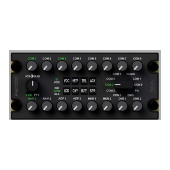
PS Engineering PAC45J Audio Selector Panel and Intercom System Installation and Operator’s Manual Appendix A – PAC45J Installation Drawings Figure 5-1 - CTL45J Front View Figure 5-2 CTL45J Top View 200-045-2000 Appendix A November 2020... - Page 38 PS Engineering PAC45J Audio Selector Panel and Intercom System Installation and Operator’s Manual Figure 5-3 - HUB45AR Top View P453 P451 J452 J454 Figure 5-4 - HUB45AR Rear Connector View 200-045-2000 Appendix A November 2020...
- Page 39 PS Engineering PAC45J Audio Selector Panel and Intercom System Installation and Operator’s Manual BLUETOOTH ANT CONN J455 Figure 5-5 HUB4A5R Front View Figure 5-6 - HUB45AR Side Views 200-045-2000 Appendix A November 2020...
-
Page 40: Appendix B - Radio Interconnect Wiring
Com 8 Mic Key Com 8 Mic Low Because of the labeling flexibility on the PAC45J System, the nomenclature on the CTL45J may not match the wiring diagram. Shown here are the switch positions for each of the available inputs. -
Page 41: Appendix C - Intercom Interconnect Wiring
PS Engineering PAC45J Audio Selector Panel and Intercom System Installation and Operator’s Manual Appendix C – Intercom Interconnect Wiring J451 P ilot M ic Audio Hi P ilot M ic Lo P ilot M ic PTT Copil ot Mic Audio Hi... -
Page 42: Appendix D - Control Head Interconnect Wiring
PS Engineering PAC45J Audio Selector Panel and Intercom System Installation and Operator’s Manual Appendix D – Control Head Interconnect Wiring PAC45 HUB45R LRU RX- RS422 TX - RX+ RS422 TX + RS422 RX - RS422 RX + PILOT CTL45A HEAD... - Page 43 PS Engineering PAC45J Audio Selector Panel and Intercom System Installation and Operator’s Manual 8.1.1 EFIS Interface PAC45 HUB LRU RX- RS422 TX - PILOT RX+ RS422 TX + EFIS RS422 RX - INTERFACE RS422 RX + J455 P455 P454 RX- RS422 TX -...
-
Page 44: Appendix E, Unit Connector Wiring Reference
PS Engineering PAC45J Audio Selector Panel and Intercom System Installation and Operator’s Manual Appendix E, Unit Connector Wiring Reference 9.1 J451 Connections J451 COM 1 C OM 1 MIC AU D IO H I C OM 1 MIC KEY S WIT CH... -
Page 45: J452 Connections
PS Engineering PAC45J Audio Selector Panel and Intercom System Installation and Operator’s Manual 9.2 J452 Connections Com 1 Audio Hi COM 1 Com 1 Lo PAC45A CONNECTOR P452 MALE ON HARNESS Com 2 Audio Hi COM 2 Com 2 Audio Low... -
Page 46: J453 Connections
PS Engineering PAC45J Audio Selector Panel and Intercom System Installation and Operator’s Manual 9.3 J453 Connections J453 FEMALE ON HARNESS GROUND GROUND GROUND GROUND GROUND ALERT 1 ALERT 2 ALERT 3 ALERT 4 ALERT 5 ALERT 6 ALERT 7 ALERT 8 ALERT 9 ALERT PGM &... -
Page 47: J455 Connections
PS Engineering PAC45J Audio Selector Panel and Intercom System Installation and Operator’s Manual 9.4.1 EFIS Interface P 45 4 M A LE O N H A R N E S S P ILO T E FIS S E R IA L... -
Page 48: Appendix F - Instructions For Faa Form 337 And Continuing Airworthiness
Aircraft equipment list, weights and balance amended. Compass compensation checked. A copy of the operation instruc- tions, contained in PS Engineering document 202-045-(XXXX), revision ( ), dated ( ), is placed in the aircraft records. All work accomplished listed on Work Order 10.2 Instructions for Continuing Airworthiness, Audio System... -
Page 49: Appendix G - Rtca Do160G Environmental Qualification Form
PAC45J Audio Selector Panel and Intercom System Installation and Operator’s Manual Appendix G – RTCA DO160G Environmental Qualification Form 11.1 Model Number PAC45J Audio Selector Panel/Intercom Remote Hub Part Number: 050-045-( ) FAA TSO Number: C139a, Manufacturer: PS Engineering Incorporated 9800 Martel Road... -
Page 50: Model Number Ctl45J, Audio Selector Control Panel
PS Engineering PAC45J Audio Selector Panel and Intercom System Installation and Operator’s Manual 11.2 Model Number CTL45J, Audio Selector Control Panel Part Number: 050-045-(20, -40XX) FAA TSO Number: C139a Manufacturer: PS Engineering Incorporated 9800 Martel Road Lenoir City TN 37772...
Need help?
Do you have a question about the PAC45J and is the answer not in the manual?
Questions and answers