Table of Contents
Advertisement
Quick Links
Advertisement
Table of Contents

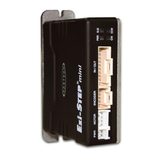
Summary of Contents for Fastech Ezi-Step Mini
- Page 1 Operating Manual www.fastech-motions.com...
-
Page 2: Table Of Contents
● ● ● ● ● ● ● ● ● ● ● ● ● ● ● ● ● ● 3. Ezi-STEP MINI Part Numbering ... -
Page 3: Precautions
·This manual describes handling, maintenance, repair, diagnosis and troubleshooting of Ezi-STEP MINI. ·Before operating Ezi-STEP MINI, thoroughly read this manual. ·After reading the manual, keep the manual near the Ezi-STEP MINI so that any user can read the manual whenever needed. - Page 4 Otherwise, an electric shock or a fire may occur. Warning The case of the Ezi-STEP MINI is insulated from the ground of the internal circuit by the condenser. Ground the Ezi-STEP MINI. Otherwise, an electric shock or a fire may occur.
- Page 5 Attention Make all input signals to OFF before supply input voltage to Ezi-STEP MINI. The machine may get damaged or the user may get injured by motor operation. All parameter values are set by default factory setting value. Change this value after reading this manual throughly.
-
Page 6: Main Characteristics
Microstep and Filtering Drive Output Signal Monitoring High precision Microstep function and Filtering Ezi-STEP MINI provides loss of step, run/stop, over- The high-performance MCU operates at step resolutions current, over-heat, over-voltage, power and motor of 1.8 ° up to maximum 0.0072 ° (1/250 steps) and Ezi- connection alarms that can be monitored by the STEP adjusts PWM control signal in every 25 μ... -
Page 7: Ezi-Step Mini Part Numbering
3. Ezi-STEP MINI Part Numbering 4. Standard Combination Ezi-STEP-MI-42M-BK-□ Unit Part Motor Model Drive Model Number Number Number Ezi-STEP-MI-20M BM-20M EzStep-MI-20M Ezi-STEP-MI-20L BM-20L EzStep-MI-20L Product Name Ezi-STEP-MI-28S BM-28S EzStep-MI-28S Ezi-STEP-MI-28M BM-28M EzStep-MI-28M Drive Series Type Ezi-STEP-MI-28L BM-28L EzStep-MI-28L Ezi-STEP-MI-42S BM-42S... -
Page 8: Specifications Of Drive
Alarm, Run/Stop (Photocoupler Output) : Up to the resolution of 10,000[ppr], maximum speed can be reached by 3,000[rpm] and with the resolution more than 10,000[ppr], maximum speed shall be reduced accordingly. 7. Dimensions of Drive [mm] 82.8 69.8 www.fastech-motions.com - 8... -
Page 9: Specifications Of Motor
Motor Voltage : 0.012 0.12 0.010 0.10 0.008 0.08 0.006 0.06 0.004 0.04 0.002 0.02 1,000 1,500 2,000 2,500 3,000 1,000 1,500 2,000 2,500 3,000 Speed[rpm] Speed[rpm] Ezi-STEP-MI-42 series Motor Voltage : 42XL 1,000 1,500 2,000 2,500 3,000 Speed[rpm] www.fastech-motions.com - 9... -
Page 10: Dimensions Of Motor [Mm]
0.075 A ±0.2 ±0.2 4-M2.5 DP2.5 Model name Length(L) BM-28S BM-28M 4-23 BM-28L ±0.15 ±0.5 ±1 □ 28 ±0.5 0.075 ±0.2 4-M3 DP4.5 ±0.2 Model name Length(L) BM-42S BM-42M 4-31 ±0.2 ±0.5 ±1 BM-42L □ 42 BM-42XL www.fastech-motions.com - 10... -
Page 11: Notes On Installation
3) If the temperature of the product case is higher than 50℃, radiate heat of the outside to cool down. 4) Do not install Ezi-STEP MINI under direct rays, near magnetic or radioactive objects. 5) If you set more than 2 drives, you must set over 20mm horizontally and over 50mm vertically as shown below. -
Page 12: Drive Status Led
12.3 Resolution Setting Switch(SW1.5~1.8) The Number of pulse per revolution. Switch Position Switch Position Pulse/ Pulse/ Revolution Revolution 6,400 1,000 8,000 1,600 10,000 2,000 20,000 3,200 25,000 3,600 36,000 4,000 40,000 5,000 50,000 *1 : Default: 10,000 www.fastech-motions.com - 12... -
Page 13: Rotational Direction Setting Switch(Sw2.5)
/B Phase Output CW-(Pulse-) Input /A Phase Output CCW+(Dir+) Input A Phase Output CCW-(Dir-) Input 1 2 3 4 Alarm Output 12.8 Power Connector(CN4) Run/Stop Output Alarm Reset Input Function EXT_GND Input 24VDC Input EXT_24VDC Input Input www.fastech-motions.com - 13... -
Page 14: System Configuration
Power Cable Length supplied 30cm Max. Length 13.1 Options ① Signal Cable ③ Power Cable Available to connect between Input/Output Control System Available to connect between Power and Ezi-STEP MINI. and Ezi-STEP MINI. Item Length [m] Remark Item Length [m] Remark CMNB-P-□... -
Page 15: Connector Specifications
(CN3) Terminal SPHD-001T-P0.5 Motor Housing 5557-04R Motor Side MOLEX Terminal 5556T Signal Housing 501646-2000 MOLEX (CN1) Terminal 501648-1000(AWG 26~28) ※ Above connector is the most suitable product for the drive applied. Another equivalent connector can be used. www.fastech-motions.com - 15... -
Page 16: External Wiring Diagram
Careful connection will be required to ※ When connects I/O cable between controller and drive, please turn off the power protect the drive from any damages. of both controller and drive, in order to protect the drive from any damage. www.fastech-motions.com - 16... -
Page 17: Control Signal Input/Output Description
[ON], cancel Alarm output. Before cancel the Alarm output, have to remove the source of alarm. [Caution] If Alarm Reset input signal still remains [ON], motor will be Free state. Keep in mind to change [ON]→[OFF] state. www.fastech-motions.com - 17... -
Page 18: Appendix
Appendix Extension Cable for Motor ■ For cable extension between Motor and Drive. WIRING DIAGRAM Connector of Drive Connector of Motor wiring Pin layout Pin number Pin number Pin layout www.fastech-motions.com - 18... - Page 19 MEMO www.fastech-motions.com - 19...
- Page 20 · User manual are subject to change without notice to improve the product or quantitative changes in specifications and user’s manual. · Ezi-STEP is registered trademark of FASTECH Co., Ltd in the national registration ⓒ Copyright 2007 FASTECH Co., Ltd. May 28, 2021 Rev.2...

Need help?
Do you have a question about the Ezi-Step Mini and is the answer not in the manual?
Questions and answers